Tappet
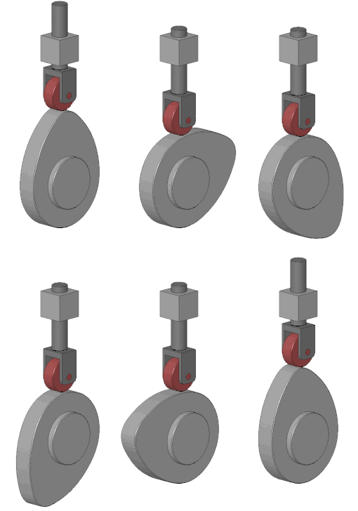
A tappet is most commonly a component in an internal combustion engine which converts the rotating motion of the camshaft into linear motion of the valves, either directly or indirectly.

An earlier use of the term was for part of the valve gear in beam engines beginning in 1715. The term is also used for components in pneumatic cylinders and weaving loom.
Beam engines
.jpg.webp)
The first recorded use of the term tappet is as part of the valve gear in the 1715 Newcomen engine, an early form of steam engine. Early versions of the Newcomen engines from 1712 had manually operated valves, but by 1715 this repetitive task had been automated through the use of tappets. The beam of the engine had a vertical 'plug rod' hung from it, alongside the cylinder. Adjustable blocks or 'tappets' were attached to this rod and as the beam moved up and down, the tappets pressed against long levers or 'horns' attached to the engine's valves, working the cycle of steam and injection water valves to operate the engine.[1]
This operation by tappets on a plug rod continued into the early twentieth century with the Cornish engine.[2]
From the 19th century onwards, most steam engines used slide valves or piston valves, which do not require the use of tappets.
Internal combustion engines

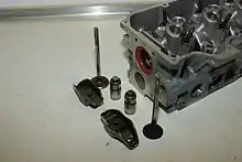
In an internal combustion engine, a tappet (also called a 'valve lifter' or 'cam follower')[3][4][5] is the component which converts the rotation of the camshaft into vertical motion which opens and closes the intake or exhaust valve. The types of valve lifters (i.e. tappets) commonly used by automotive engines are solid lifters, hydraulic lifters and roller lifters.[6][7]
An alternative to the tappet is the 'finger follower', which is a pivoting beam that is used to convert the camshaft rotation into opening and closing of a valve. Finger followers are used in some high-performance dual overhead camshaft engines (instead of bucket tappets), most commonly in motorcycles and sports cars.[8]
To reduce wear from the rotating camshaft, the tappets are usually circular and allowed, or even encouraged, to rotate. This avoids grooves developing from the same point of the tappet always running on the same point of the camshaft. However, in some relatively small engines with many cylinders (such as the Daimler '250' V8 engine), the tappets were small and non-rotating.
Most 'flat' tappets (i.e. without rollers) usually contain a slight convex radius which creates a subtle mushroom-shaped surface, since a perfectly flat surface leads to 'slamming' against a steep camshaft face.
Adjusting the tappets
A common, yet imprecise, use of the term 'tappet' is the engine maintenance task referred to as "adjusting the tappets" in an overhead valve (OHV) engine, which has been a widely used engine configuration since the 1940s. The task involves adjusting the clearance of tappet from the camshaft, however the adjustment is not actually made to the tappets themselves.
On most OHV engines, the adjustment was made by turning a screw set in the end of the rocker that pressed on the end of the pushrod. With the engine rotated to give the widest gap between the camshaft and a particular tappet, the rocker screw was adjusted until this gap was at the correct spacing, as measured with the use of a feeler gauge. If the gap was too wide, this could result in an audible 'tappet rattle' from the rocker cover. If the gap was too narrow, this could result in engine damage such as bent pushrods or burnt valves. The adjusting screw was locked by a locknut. Failure of the locknut to hold the adjustment in place could cause catastrophic engine failure, which has led to fatal aircraft crashes.[9]
On some OHV engines in the 1960s, such as the Ford Taunus V4 engine and Opel CIH engine, the tappet adjustment was done by setting the height of the rocker pivot point (rather than the typical method of a rocker-end adjustment screw). On the 1965-1970 versions of the Opel CIH engine with solid tappets, the tappet adjustment was conducted with the engine running.[10]
Hydraulic tappets

A hydraulic tappet, also known as a "hydraulic lash adjuster", contains a small hydraulic piston that becomes filled with pressurised engine oil.[4][11] the piston acts as a hydraulic spring that automatically adjusts the tappet clearance according to the oil pressure. Although the movements of the piston are small and infrequent, they are sufficient to make the valve actuation self-adjusting so that there is no need to manually adjust the clearance of the tappets.
Hydraulic tappets depend on a supply of clean oil at the appropriate pressure. When starting a cold engine, with low oil pressure, hydraulic tappets are often noisy for a few seconds, until they position themselves correctly.
Roller tappets
Early automotive engines used a roller at the contact point with the camshaft,[12]: 44 however as engine speeds increased, 'flat tappets' with plain ends became far more common than tappets with rollers. However in recent times, roller tappets and rocker arms with roller tappet ends have made a resurgence due to the lower friction providing greater efficiency and reducing drag. [7]
Sidevalve engines
.jpg.webp)
In a sidevalve engine— a common design for car engines until the 1950s— the valves are mounted at the sides of the cylinder and face upwards. This means that the camshaft could be placed directly beneath the valves, without the need for a rocker. With lower cylinder blocks, the tappets could drive the valves directly without needing even a push rod.[4][13]
Sidevalve engines also required regular adjustment of the tappet clearance, and in this case it was the tappets themselves that were adjusted directly. Small access plates were provided on the sides of the cylinder block, giving access to the gap between the valves and tappets. Some tappets had a threaded adjuster, but simpler engines could be adjusted by grinding down the ends of the valve stem directly. As the tappet adjustment always consisted of expanding the clearance (re-grinding valves into their valve seats during de-coking makes them sit lower, thus reducing the tappet clearance), adjustment by shortening the valve stems was a viable method. Eventually the valves would be replaced entirely, a relatively common operation for engines of this era.
Pushrod engines
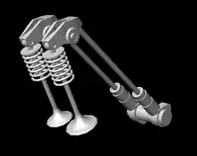
In a pushrod engine, the tappets are located down in the engine block and operate long, thin pushrods which transfer the motion (via the rocker arms) to the valves located at the top of the engine.[14]
Single overhead camshaft engines
In a single overhead camshaft (SOHC) engine, the tappets are integrated into the design of the rocker arms as one piece, since the camshaft interacts with the rocker arm directly.
Mass-production of SOHC engines for passenger cars became more common in the 1970s, in the form of crossflow cylinder heads with overhead rockers located directly above a single overhead camshaft, as a more efficient design which could be cost-effectively manufactured. The 1970-2001 Ford Pinto engine was one of the first mass-production engines to use an SOHC design with a toothed cambelt.[15] In this configuration, the rockers combine the function of sliding tappet, rocker and adjustment device. Adjustment of the valve clearance was usually by a threaded stud at the valve end of the rocker. The linear sliding tappet side often had a high rate of wear and demanded careful lubrication with oil containing zinc additives.
A relatively uncommon design of an SOHC camshaft with four valves per cylinder was first used in the 1973-1980 Triumph Dolomite Sprint inline-four engine, which used a camshaft with 8 lobes that actuated the 16 valves via a clever arrangement of rocker arms.[16][17]
Double overhead camshaft engines
.jpg.webp)
Double overhead camshaft (DOHC) engines were first developed as high performance aircraft and racing engines, with the camshafts mounted directly over the valves and driving them through a simple 'bucket tappet'. Most engines used a crossflow cylinder head with the valves in two rows in line with their corresponding camshaft.
The tappet clearance adjustment is typically set using a small shim, located either above or below the tappet. Shims were made in a range of standard thicknesses and a mechanic would swap them to change the tappet gap. In early DOHC engines, the engine would first be assembled with a default shim of known thickness, then the gap measured. This measurement would be used to calculate the thickness of shim that would result in the desired gap. After installation of the new shim, the gaps would then be measured again to verify that the clearance was correct. As the camshaft had to be removed to change the shims, this was a very time consuming operation (especially since the position of the camshaft could vary slightly each time it was re-installed).
Later engines used an improved design where the shims were located above the tappets, which allowed each shim to be changed without removing either the tappet or camshaft. A drawback of this design is that the rubbing surface of the tappet becomes the surface of the shim, which is a difficult problem of mass-production metallurgy. The first mass production engine to use this system was the 1966-2000 Fiat Twin Cam engine, followed by engines from Volvo and the water-cooled Volkswagens.[18]
Other uses
.jpg.webp)
The term 'tappet' is also used, obscurely, as a component of valve systems for other machinery, particularly as part of a bash valve in pneumatic cylinders. Where a reciprocating action is produced, such as for a pneumatic drill or jackhammer, the valve may be actuated by inertia or by the movement of the working piston. As the piston hammers back and forth, it impacts a small tappet, which in turn moves the air valve and so reverses the flow of air to the piston.[19]
In weaving looms, a tappet is a mechanism which helps form the shed or opening in the warp threads (long direction) of the material through which the weft threads (side to side or short direction) are passed. The tappets form the basic patterns in the material such as plain weave, twill, denim, or satin weaves. Harris tweed is still woven on looms in which tappets are still used.
Tom and Ray Magliozzi, cohosts of the NPR radio show Car Talk, used the nickname "Click and Clack, the Tappet Brothers".[20]
See also
References
- The Newcomen Memorial Engine. Dartmouth, England: Newcomen Society.
- Woodall, Frank D. (1975). Steam Engines and Waterwheels. Moorland. pp. 31–34. ISBN 0903485354.
- Setright & Anatomy of the Motor Car, p. 33
- Hillier, V.A.W. (1981). Fundamentals of Motor Vehicle Technology (4th ed.). Stanley Thornes. p. 44. ISBN 0-09-143161-1.
- "Valve system operation" (PDF). www.thecarguys.net. Retrieved 11 February 2020.
- "Hydraulic vs. Solid Lifters". www.summitracing.com. Retrieved 11 February 2020.
- "What is the difference between a flat tappet and a roller camshaft?". www.summitracing.com. Retrieved 11 February 2020.
- "About Those Finger Followers On Sportbike Engines". www.cycleworld.com. Retrieved 11 February 2020.
- Alexander, Robert Charles (1999). The Inventor of Stereo: The Life and Works of Alan Dower Blumlein. Focal Press. ISBN 0-240-51628-1.
- "Tuning the 1.9 Litre Opel (Part I)" (PDF). www.opelclub.com. Retrieved 21 February 2020.
- Setright & Anatomy of the Motor Car, p. 33
- Hillier, Victor Albert Walter (1991). Fundamentals of Motor Vehicle Technology. Nelson Thornes. ISBN 978-0-7487-0531-3. Retrieved 11 February 2020.
- Setright & Anatomy of the Motor Car, p. 34
- Setright, L. J. K. (1976). "Valve gear". In Ian Ward (ed.). Anatomy of the Motor Car. Orbis. pp. 29–36. ISBN 0-85613-230-6.
- "Ford SOHC (Pinto) Tuning Guide". www.burtonpower.com. Retrieved 20 March 2020.
- "Dolomite History". www.triumphclub.co.nz. Retrieved 20 March 2020.
- "Triumph Dolomite Sprint". www.classiccars4sale.net. Retrieved 20 March 2020.
- Setright & Anatomy of the Motor Car, p. 34
- Kennedy, Rankin. The Book of Modern Engines and Power Generators. Vol. VI (1912 ed.). London: Caxton. p. 162-166.
- "Tom and Ray Magliozzi". NPR. Retrieved 16 August 2023.