Fialka
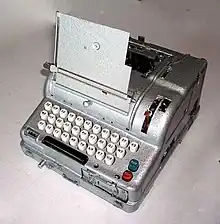
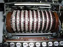
In cryptography, Fialka (M-125) is the name of a Cold War-era Soviet cipher machine. A rotor machine, the device uses 10 rotors, each with 30 contacts along with mechanical pins to control stepping. It also makes use of a punched card mechanism. Fialka means "violet" in Russian. Information regarding the machine was quite scarce until c. 2005 because the device had been kept secret.[1]
| Fialka | |
|---|---|
 The advanced Russian cipher machine Fialka (M-125) has only recently been made known to the public. | |
| Classification | Rotor machine |
| Industry | Military |
| Powered | Yes |
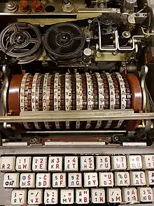
Fialka contains a five-level paper tape reader on the right hand side at the front of the machine, and a paper tape punch and tape printing mechanism on top. The punched-card input for keying the machine is located on the left hand side. The Fialka requires 24 volt DC power and comes with a separate power supply that accepts power at 100 to 250 VAC, 50–400 Hz by means of an external selector switch.[2]
The machine's rotors are labelled with Cyrillic, requiring 30 points on the rotors; this is in contrast to many comparable Western machines with 26-contact rotors, corresponding to the Latin alphabet. The keyboard, at least in the examples of East German origin, had both Cyrillic and Latin markings. There are at least two versions known to exist, the M-125-MN and the M-125-3MN. The M-125-MN had a typewheel that could handle Latin and Cyrillic letters. The M-125-3MN had separate typewheels for Latin and Cyrillic. The M-125-3MN had three modes, single shift letters, double shift with letters and symbols, and digits only, for use with code books and to superencrypt numeric ciphers.
Encryption mechanism


The Fialka rotor assembly has 10 rotors mounted on an axle and a 30 by 30 commutator (Kc 30x30). The commutator consists of two sets of 30 contact strips set at right angles to each other. A punched card is placed between the two sets of contacts via a door on the left hand side of the unit. Each punched card has 30 holes, with exactly one hole per row and column pair, and thereby specifies a permutation of the 30 rotor contact lines. This feature is comparable to the plug board on the Enigma machine. A triangular plate was used to enter the null permutation for testing purposes.
There are two types of rotors:
- disassemblable (zerlegbar) rotors, used with the M-125-3MN. The rotorset name is "PROTON." The disassemblable rotors consist of an insert with electrical contacts and scramble wiring, and an outer ring with mechanical pins whose presence or absence control rotor stepping. As part of the key setup, the stepping control pins can be rotated relative to the outer ring. The inner, electrical ring can also be rotated relative to the outer ring and can be inserted in one of two ways, with side 1 or side 2 up.
- unitary rotors, used with the M-125-MN. These have both electrical contacts and mechanical pins. The only key adjustment is the order of the rotors on the axle and the initial rotor settings. There is one combination for the disassemblable rotors that is compatible with the unitary rotor. One East German manual that has become public contains typed-in and hand written addenda that suggest the East Germans, at least, later stopped using the added features of the disassemblable rotors and only used them in unitary compatibility mode.
Adjacent rotors step in opposite directions. A spare rotor assembly could be kept in the unit's top cover. The Fialka machines were originally delivered with two sets of rotors, one in the machine assemblage and one set supplied in a metal cylinder inside the dustcover.[3] The singly most crucial flaw in the Enigma design was that letter substitutions were reciprocal and that in particular a letter could never encrypt to itself.[4] The Russians clearly learned from this in designing Fialka such that it is possible for a letter to encrypt to itself.[5]

Keying material
The keying material for the Fialka consists of a daily key book, a message key book and a message identifier book for broadcast traffic. The daily key book contains day keys for one month. A day key consists of a key table (in Cyrillic) and a punched card. For fixed rotor systems, the key table specifies the order of the rotors on the axle and the initial rotor settings to be used to decrypt the indicator of broadcast messages. As its name implies, the day key is valid (has a cryptoperiod in NSA parlance) for 24 hours and was changed at 00:01 hours. For the disassemblable rotors, the table also specifies the electrical insert for each outer rotor, which side was to be up, and the orientation of the insert relative to the outer rotor. Here is a sample M-125-3NM day key table for use on the 14th of the month:
- ИДЖЗА ВКБГЕ 14
- OCAHE PTБВЕ
- БДВИА ГЕЗКЖ
- 2II22 I22I2
- КУЛКЮ ЫХВУГ
The message key table contained the initial rotor settings to be used with each message. A message key was never to be used more than once. The keying material was distributed in a foil-covered package, with the daily key tables and punched cards fan-folded in a pouch with perforations between each item. The other tables were in a side pouch.
Design measures against information leakage
Design factors in various cryptographic devices can result in the physical leakage of information that may compromise the security of the system to varying degrees (see TEMPEST), the following describe appropriate counter measures that were taken in the design of Fialka.
Power supply unit
Fialka draws differing amounts of current depending on which (5-bit) encoded letter is printed or paper punched. If the power supply was plugged into the mains there would be an opportunity for the small power fluctuations to be observed by an eavesdropper.
In order to mask any mains supplied power fluctuations a data cable fed back from the Fialka machine to the power supply unit indicating which letter was being output allowing the supply to compensate for the differing loads. The supply was designed with a compensating circuit with five artificial load resistors which would be powered depending on the signal from the feedback cable.[6]
Comparison with other rotor machines
The Fialka design is derived from the Swiss NEMA, but the NEMA only had 5 electrical rotors vis-à-vis the Fialka's 10, and furthermore NEMA lacked a punched card commutator or equivalent such as a plug board. Fialka is most comparable to the U.S. KL-7 which has eight electrical rotors and also lacks a commutator, but its keyboard permutation switch eliminated the need for a reflector (which had proven to be a weakness in the Enigma system).
References
- Reuvers, Paul; Simons, Marc (June 2009). "Schlüsselgerät 41" (PDF) (Detailed description of the Russian Fialka cipher machines, 144 pages. ed.). Retrieved 6 Feb 2021.
- Reuvers, Paul; Simons, Marc (June 2009). "Schlüsselgerät 41" (PDF) (Detailed description of the Russian Fialka cipher machines, 144 pages. ed.). p. 31.
- Reuvers, Paul; Simons, Marc (June 2009). "Schlüsselgerät 41" (PDF) (Detailed description of the Russian Fialka cipher machines, 144 pages. ed.). p. 40.
- Huttenhain, Orr; Fricke (1945), OKW/Chi Cryptanalytic Research on Enigma, Hagelin and Cipher Teleprinter Messages (PDF), TICOM, p. 2
- Reuvers, Paul; Simons, Marc (June 2009). "Schlüsselgerät 41" (PDF) (Detailed description of the Russian Fialka cipher machines, 144 pages. ed.). p. 93.
- Reuvers, Paul; Simons, Marc. "Schlüsselgerät 41" (PDF) (Detailed description of the Russian Fialka cipher machines, 144 pages. ed.). p. 98.
Further reading
- Borshchevskaya, Anna (April 27, 2019). "The Soviets' Unbreakable Code: The hidden history of the Fialka espionage machine". Foreign Policy. Retrieved 2021-12-03.
- Gu, Matthew (n.d.). "Fialka: The Bigger, Better, Russian Enigma". Wonders & Marvels. Retrieved 2021-12-03.
- National People's Army (December 1978). "M-125 Operation (Nutzung) manual, DV A 040/1/321" (PDF) (in German). German Democratic Republic. Retrieved 2021-12-03. Scanned PDF from Dr. Tom Perera.
- Perera, Tom; Hamer, David (2005). "General Introduction: Russian Cold War Era M-125 and M-125-3MN Fialka Cipher Machines". www.w1tp.com. Enigma Museum. Retrieved 2021-12-03.
External links
- The M-125-3 Fialka cipher machine — German Spy Museum Berlin
- Russian Fialka ( = Violet ) 10-Rotor Device — by Nick Gessler
- Russian M-125 Fialka — by Jerry Proc
- Simulation of M125MN and M125-3MN find under