L&YR 2-10-0 (Hughes)
The L&YR 2-10-0 was a prospective design for a class of 2-10-0 steam locomotives on the Lancashire and Yorkshire Railway. Initial designs were made by George Hughes between 1913 and 1914, but none of the class were built. If they had been, these would have been the UK's first 10-coupled locomotives in regular service.
| L&YR 2-10-0 | |||||||||||||||||||||||||||||||||||||||||||||||||||||||||||||||||||||||||||||||||||
|---|---|---|---|---|---|---|---|---|---|---|---|---|---|---|---|---|---|---|---|---|---|---|---|---|---|---|---|---|---|---|---|---|---|---|---|---|---|---|---|---|---|---|---|---|---|---|---|---|---|---|---|---|---|---|---|---|---|---|---|---|---|---|---|---|---|---|---|---|---|---|---|---|---|---|---|---|---|---|---|---|---|---|---|
| |||||||||||||||||||||||||||||||||||||||||||||||||||||||||||||||||||||||||||||||||||
| |||||||||||||||||||||||||||||||||||||||||||||||||||||||||||||||||||||||||||||||||||
| |||||||||||||||||||||||||||||||||||||||||||||||||||||||||||||||||||||||||||||||||||
| |||||||||||||||||||||||||||||||||||||||||||||||||||||||||||||||||||||||||||||||||||
Background
Locomotives with ten driving wheels were rare in British railway history. One specialist exception,[lower-roman 1] the GER Decapod, had been built in 1902, but the main heavy mineral locomotive design was the 0-8-0, on both the L&YR and the LNWR. Train weights were increasing though and there was some demand for a more powerful locomotive, particularly for the steep gradients across the Pennines from the Lancashire Coalfield to the port of Goole. It was felt that a more powerful single locomotive would avoid the need for double-heading on coal trains.[2]
In August 1913, John Aspinall was on holiday in the spa and railway town of Bad Homburg, Germany.[3] Impressed by the capacity of the new Prussian G 10 0-10-0 heavy freight locomotives, Aspinall wrote to Hughes requesting a report on the extent of double heading for the trans-Pennine coal traffic, which Hughes provided in September. Inspired by recent work in Belgium, which had shown savings of 19% in coal consumption by avoiding it, Hughes suggested the use of a single large locomotive, emphasised the need to use it at full capacity and also rejected a proposed concept for a 2-8-2 in favour of a 2-10-0.[3][lower-roman 2]
Concept
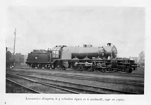
At the Brussels International exhibition of 1910 the Belgian engineer Jean-Baptiste Flamme exhibited his new Type 10 Pacific, the most powerful European locomotive of the time. This was a four-cylinder superheated passenger locomotive with a distinctive tapered boiler of Flamme's design. Flamme used the large Belgian loading gauge to its most and made the round-topped boiler particularly high. The tapered section ahead of the firebox reduced to a boiler barrel which allowed enough height above for the steam dome.
Hughes had been influenced by Flamme, by his views on superheating and on the testing of locomotives by the use of dynamometer cars. Flamme's design had the novel feature of a mechanical integrator to calculate drawbar horsepower-hours directly. He was encouraged to build such a car for the L&YR.[4][5]
In 1911, a party of senior L&YR officials from Horwich had visited Flamme in Belgium.[4] They were particularly interested in the Type 10 and also the related Belgian State Railways Type 36 2-10-0. These two designs shared the same boiler. The L&YR had little use for such a powerful passenger locomotive, but the 2-10-0 was of great interest. The 2-10-0 was of conventional layout, with the two rear driving axles set beneath the firebox grate and ashpan. The pacific though, with the same boiler, required its higher axles to be placed ahead of the firebox. This required a carrying axle below the firebox and also placed the four cylinders ahead of the smokebox, beneath a prominent flat platform.
Design
Hughes' first design proposal in September 1913 put forward a number of principles. None of these were radical, but they represented the best features of British locomotive design at the time, together with Flamme's influence. Although Horwich would later be overshadowed by Stanier's work during the LMS period, at this time they considered themselves to be one of the leading British locomotive designers.[6]
- Superheating, a developing practice at the time, which Hughes had experience of with smaller classes, although the valve and lubrication problems were still an issue. The use of piston valves was a response to this, their piston ring sealing working better at these increased steam temperatures than the flat faces of slide valves had done.
- Large grate area, and large boiler.
- A large grate allowed a shallow fire, capable of burning the hard local coal. The large boiler surface avoided the need to 'force' the boiler, and the excess coal consumption that entailed.
- Improved cylinder design and porting, with improved valve gear
- The importance of this was increasingly recognised at this time, by those engineers such as Hughes and George Jackson Churchward, who were following developments in continental best practice. Churchward's Star class and its combination of superheating with long-travel, large-diameter piston valves represented the best front-end performance yet achieved in Britain.[7]
- The Walschaerts valve gear was another Belgian influence and was a change from the previous Stephenson or Joy valve gears used previously. With the 4-6-0 Dreadnoughts of 1908,[8] Hughes' reputation as an engineer and innovator had suffered and these locomotives would later be improved by rebuilding, part of which was to change their Joy valve gear to Walschaerts.[7]
- Four cylinder simple, rather than compound.
- Although he had experimented with compounding, Hughes chose to use four simple cylinders here. These gave better balance and also permitted just two sets of outside valve gear, with the inside valves being operated by rockers. This freed up more space between the frames, allowing for a stronger crank axle, connecting rods and big ends.
- Despite this being the era for the adoption of the (also Belgian) Belpaire firebox, which Hughes had introduced on his other designs and rebuilding work,[lower-roman 3] Flamme now considered it 'obsolete'.[9] Flamme's new design was for a round-topped firebox of the maximum possible size, and with radial firebox stays rather than the older and troublesome girder stays. The tapered rear ring of the boiler allowed the highest firebox to be used with a practical diameter of boiler, even though the British loading gauge meant that there could be no dome.
- Flexible wheelbase
- The new layout and the length of the wheelbase were a concern, and a means was needed to provide some flexibility.[lower-roman 4] Flamme had used a Krauss-Helmholtz bogie where the front carrying axle and the leading driver were articulated as a bogie.
- Alloy steels, with nickel and chromium additives, were in development at this time and they were to be used for the most highly stressed parts of the motion.
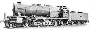
An initial design for a four-cylinder 2-10-0 was produced. An outline drawing, dated 18 June 1914, is shown in (Marshall (3) 1972).[10][11] The calculated tractive effort of 53,328 lbf (237,000 N)[12] would be exceptional for this time; the contemporary Class 31 0-8-0 was only 34,055 lbf (151,000 N) in comparison.
Hughes' design was strongly influenced by Flamme's, particularly for its boiler. The round-topped boiler almost filled the loading gauge, with the firebox wrapper the height of the cab. Even though it was also tapered, the boiler had to be domeless, owing to the lack of clearance and even the safety valves had to be moved to the side, rather than the usual position on top.[12] The boiler pressure was lowered from 200 to 180 psi, but the slightly smaller wheels kept the tractive effort high. The large grate area of 50 sq ft (4.6 m2) would have provided adequate evaporative capacity, but would also have been a challenge for the fireman.[12][13]
The cylinders were directly below the smokebox and moderately inclined, with all four cylinders driving on the third axle. The crosshead was, unusually, a single bar type. Walschaerts valve gear was used. The piston rods are particularly long, allowing space for a rocker arm on the valve rods, between the valve chest and the combination lever, to drive the inner valves.
The front carrying axle was simplified to a conventional Bissell truck, carried on a long radius pivot under the first driven axle, of almost 9 feet (3 m). The two rear driving axles were beneath the ashpan, although this early design does not make it clear how the small space here was managed. The Dreadnoughts had already suffered from a lack of air supply here.[7]
Owing to the length of the locomotive, the tender was kept to a short 6-wheeled pattern,[12] rather than the existing 8-wheeled designs of the 0-8-0 locomotives, so that the overall locomotive would still fit onto existing turntables. This was taller though, so its capacity was increased from 5 tons and 3,600 gallons[14] to 6 tons and 4,500 gallons.[10] Despite this increase, it was still described as looking like "an elephant harnessed to a hand-cart".[15]
The outbreak of the Great War only a month after this drawing meant that there was no longer time for new speculative designs, and so none were built.[12][16] Its effects also prevented Hughes from the much-needed rebuilding work on the Dreadnoughts.[7]
Post-War
In 1923, just after the Grouping, a series of new designs were drawn up at Horwich in an attempt to set the direction of future locomotive development, rather than the Crewe or Derby influences. John Billington worked on a wide-firebox pacific based on the newly rebuilt 4-6-0 Dreadnoughts, a new 2-8-2 heavy freight locomotive and also a 4-cylinder 2-10-0, based on Hughes' Flamme-inspired design.[17] These designs were not well received by the new LMS directors at Euston, and Horwich would produce few influential designs thereafter. The 2-10-0 in particular, and its long wheelbase, was opposed by the civil engineering department.[18]
References
- There are several L&YR references to a 'ten-wheeled shunting engine', but these are to Lot 59, the 0-8-2T L&YR Class 32.[1]
- At this pre-war time, coal costs were the primary matter in mind. Post-war, crew costs and their rising wages would also become significant.
- Such as his rebuilding of the Aspinall Class 5
- The flangeless drivers of Hoy's large Class 26 2-6-2 tanks had not been a success if the track was less than perfect.
- Marshall (3) (1972), pp. 178–180.
- Marshall (3) (1972), p. 188.
- Marshall (3) (1972), p. 188–190.
- Marshall (3) (1972), p. 186.
- "George Hughes". Steamindex.
- Marshall (3) (1972), pp. 190–191.
- Marshall (3) (1972), p. 181.
- Hughes, George (17 July 1909). "Horwich locomotives". Proc. Inst. Mech. Eng.
- Marshall (3) (1972), p. 190.
- Marshall (3) (1972), p. 189.
- Walford & Harrison (2008), pp. 1–3, 296
- Barnes (1985), pp. 24–25
- Marshall, John (1997). "George Hughes of Horwich, part 2". British Railway Journal. Vol. 7, no. 60. pp. 112–123.
- Marshall (3) (1972), p. 148.
- Mason (1954), p. 152.
- Marshall (3) (1972), pp. 188–191
- "Horwich engineers". Steamindex.
- Marshall (3) (1972), p. 191.
- Barnes, Robin (1985). "L&YR Hughes 2-10-0". Locomotives That Never Were. Jane's. pp. 24–25. ISBN 0-7106-0326-6.
- Marshall, John (1972). The Lancashire and Yorkshire Railway. Vol. 3. Newton Abbot: David & Charles. pp. 188–191. ISBN 0-7153-5320-9.
- Mason, Eric (1975) [1954]. The Lancashire and Yorkshire Railway in the Twentieth Century (2nd ed.). Ian Allan. pp. 151–152. ISBN 0-7110-0656-3.
- Walford, John; Harrison, Paul (2008). The 9F 2-10-0 Class. A detailed history of British Railways Standard Steam Locomotives. Vol. 4. Bristol: RCTS. ISBN 978-0-901115-95-9.

