Rotary kiln
A rotary kiln is a pyroprocessing device used to raise materials to a high temperature (calcination) in a continuous process. Materials produced using rotary kilns include:


They are also used for roasting a wide variety of sulfide ores prior to metal extraction.
Principle of operation
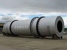
The kiln is a cylindrical vessel, inclined slightly from the horizontal, which is rotated slowly about its longitudinal axis. The process feedstock is fed into the upper end of the cylinder. As the kiln rotates, material gradually moves down toward the lower end, and may undergo a certain amount of stirring and mixing. Hot gases pass along the kiln, sometimes in the same direction as the process material (co-current), but usually in the opposite direction (counter-current). The hot gases may be generated in an external furnace, or may be generated by a flame inside the kiln. Such a flame is projected from a burner-pipe (or "firing pipe") which acts like a large bunsen burner. The fuel for this may be gas, oil, pulverized petroleum coke or pulverized coal.
Construction
The basic components of a rotary kiln are the shell, the refractory lining, support tyres (riding rings) and rollers, drive gear and internal heat exchangers.
History
The rotary kiln was invented in 1873 by Frederick Ransome.[1] He filed several patents in 1885-1887, but his experiments with the idea were not a commercial success. Nevertheless, his designs provided the basis for successful kilns in the US from 1891, subsequently emulated worldwide.
Kiln shell
This is made from rolled mild steel plate, usually between 15 and 30 mm thick, welded to form a cylinder which may be up to 230 m in length and up to 6 m in diameter.
Upper limits on diameter are set by the tendency of the shell to deform under its own weight to an oval cross section, with consequent flexure during rotation. Length is not necessarily limited, but it becomes difficult to cope with changes in length on heating and cooling (typically around 0.1 to 0.5% of the length) if the kiln is very long.
Refractory lining
The purpose of the refractory lining is to insulate the steel shell from the high temperatures inside the kiln, and to protect it from the corrosive properties of the process material. It may consist of refractory bricks or cast refractory concrete, or may be absent in zones of the kiln that are below approximately 250 °C. The refractory selected depends upon the temperature inside the kiln and the chemical nature of the material being processed. In some processes, such as cement, the refractory life is prolonged by maintaining a coating of the processed material on the refractory surface. The thickness of the lining is generally in the range 80 to 300 mm. A typical refractory will be capable of maintaining a temperature drop of 1000 °C or more between its hot and cold faces. The shell temperature needs to be maintained below around 350 °C to protect the steel from damage, and continuous infrared scanners are used to give early warning of "hot-spots" indicative of refractory failure.
Tyres and rollers

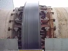
Tyres, sometimes called riding rings, usually consist of a single annular steel casting, machined to a smooth cylindrical surface, which attach loosely to the kiln shell through a variety of "chair" arrangements. These require some ingenuity of design, since the tyre must fit the shell snugly, but also allow thermal movement. The tyre rides on pairs of steel rollers, also machined to a smooth cylindrical surface, and set about half a kiln-diameter apart. The rollers must support the kiln, and allow rotation that is as nearly frictionless as possible. A well-engineered kiln, when the power is cut off, will swing pendulum-like many times before coming to rest. The mass of a typical 6 x 60 m kiln, including refractories and feed, is around 1100 tonnes, and would be carried on three tyres and sets of rollers, spaced along the length of the kiln. The longest kilns may have 8 sets of rollers, while very short and small kilns may have none. Kilns usually rotate at 0.5 to 2 rpm. The Kilns of modern cement plants are running at 4 to 5 rpm. The bearings of the rollers must be capable of withstanding the large static and live loads involved and must be carefully protected from the heat of the kiln and the ingress of dust. Since the kiln is at an angle, it also needs support to prevent it from walking off the support rollers. Usually upper and lower "retaining (or thrust) rollers" bearing against the side of tyres prevent the kiln from walking off the support rollers.
Drive gear
The kiln is usually turned by means of a single Girth Gear surrounding a cooler part of the kiln tube, but sometimes it is turned by driven rollers. The gear is connected through a gear train to a variable-speed electric motor. This must have high starting torque to start the kiln with a large eccentric load. A 6 x 60 m kiln requires around 800 kW to turn at 3 rpm. The speed of material flow through the kiln is proportional to rotation speed; a variable-speed drive is needed to control this. When driving through rollers, hydraulic drives may be used. These have the advantage of developing extremely high torque. In many processes, it is dangerous to allow a hot kiln to stand still if the drive power fails. Temperature differences between the top and bottom of the kiln may cause the kiln to warp, and refractory is damaged. Hence, normal practice is to provide an auxiliary drive for use during power cuts. This may be a small electric motor with an independent power supply, or a diesel engine. This turns the kiln very slowly, but enough to prevent damage.
Internal heat exchangers
Heat exchange in a rotary kiln may be by conduction, convection and radiation, in descending order of efficiency. In low-temperature processes, and in the cooler parts of long kilns lacking preheaters, the kiln is often furnished with internal heat exchangers to encourage heat exchange between the gas and the feed. These may consist of scoops or "lifters" that cascade the feed through the gas stream, or may be metallic inserts that heat up in the upper part of the kiln, and impart the heat to the feed as they dip below the feed surface as the kiln rotates. The latter are favoured where lifters would cause excessive dust pick-up. The most common heat exchanger consists of chains hanging in curtains across the gas stream.
Other equipment
The kiln connects with a material exit hood at the lower end and ducts for waste gases. This requires gas-tight seals at either end of the kiln. The exhaust gas may go to waste, or may enter a preheater, which further exchanges heat with the entering feed. The gases must be drawn through the kiln, and the preheater if fitted, by a fan situated at the exhaust end. In preheater installations which may have a high pressure-drop, considerable fan power may be needed, and the fan drive is often the largest drive in the kiln system. Exhaust gases contain dust, and there may be undesirable constituents, such as sulfur dioxide or hydrogen chloride. Equipment is installed to scrub these from the gas stream before passing to the atmosphere.
Differences according to the process
Kilns used for DRI production
 | ||||||
| Extraction Point | 1 | 2 | 3 | 4 | 5 | |
|---|---|---|---|---|---|---|
| Consistency of kiln discharge | solid | semiliquid | sol. (clinker) liq. (pig iron) | |||
| Preferred iron content of ore (% Fe) | 30-60 | 30-60 | 55-63 | 25-45 | 50-67 | |
| Size of ore feed (mm) | < 20 | < 20 | < 10 | 5-25[3] | < 5 | < 0.2 |
| Influence of basicity of charge (CaO/Al 2O 3) |
no influence | 0.3 | 2.8-3.0 | |||
| Maximal temperature of charge (°C) | 600-900 | 900-1100 | 1200-1300 | 1400-1500 | ||
| Oxygen removal (% O 2 extracted from Fe 2O 3) |
12 % | 20-70 | >90 | 100 | ||
| Examples of processes | Lurgi | Highveld Udy LARCO Elkem |
RN | SL/RN Krupp |
Krupp-Renn | Basset |
See also
Citations
- The Michigan Technic. UM Libraries. 1900. pp. 3–.
- Grzella, Jörg; Sturm, Peter; Krüger, Joachim; Reuter, Markus A.; Kögler, Carina; Probst, Thomas (2005). "Metallurgical Furnaces" (PDF). John Wiley & Sons. p. 7.
- For ilmenite and ferrous sands : size between 0.05 and 0.5 mm.
General and cited sources and further reading
- R. H. Perry, C. H. Chilton, C. W. Green (ed.), Perry's Chemical Engineers' Handbook (7th Ed), McGraw-Hill (1997), sections 12.56-12.60, 23.60, ISBN 978-0-07-049841-9.
- K. E. Peray, The Rotary Cement Kiln, CHS Press (1998), ISBN 978-0-8206-0367-4.
- Boateng, Akwasi, Rotary kilns: transport phenomena and transport processes. Amsterdam; Boston: Elsevier/Butterworth-Heinemann (2008), ISBN 978-0-7506-7877-3.
External links
 Media related to Rotary kilns at Wikimedia Commons