Septic drain field
Septic drain fields, also called leach fields or leach drains, are subsurface wastewater disposal facilities used to remove contaminants and impurities from the liquid that emerges after anaerobic digestion in a septic tank. Organic materials in the liquid are catabolized by a microbial ecosystem.

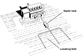
A septic drain field, a septic tank, and associated piping compose a septic system.
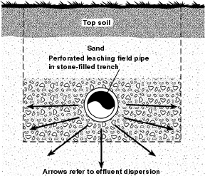
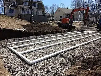
The drain field typically consists of an arrangement of trenches containing perforated pipes and porous material (often gravel) covered by a layer of soil to prevent animals (and surface runoff) from reaching the wastewater distributed within those trenches.[1] Primary design considerations are both hydraulic for the volume of wastewater requiring disposal and catabolic for the long-term biochemical oxygen demand of that wastewater. The land area that is set aside for the septic drain field may be called a septic reserve area (SRA).[2]
Sewage farms similarly dispose of wastewater through a series of ditches and lagoons (often with little or no pre-treatment). These are more often found in arid countries as the waterflow on the surface allows for irrigation (and fertilization) of agricultural land.
Design


Many health departments require a percolation test ("perc" test) to establish the suitability of drain field soil to receive septic tank effluent. An engineer, soil scientist, or licensed designer may be required to work with the local governing agency to design a system that conforms to these criteria.
A more progressive way to determine leach field sizing is by direct observation of the soil profile. In this observation, the engineer evaluates many features of the soil such as texture, structure, consistency, pores/roots, etc.
The goal of percolation testing is to ensure the soil is permeable enough for septic tank effluent to percolate away from the drain field, but fine grained enough to filter out pathogenic bacteria and viruses before they travel far enough to reach a water well or surface water supply. Coarse soils – sand and gravel – can transmit wastewater away from the drain field before pathogens are destroyed. Silt and clay effectively filter out pathogens but allow very limited wastewater flow rates.[3] Percolation tests measure the rate at which clean water disperses through a disposal trench into the soil. Several factors may reduce observed percolation rates when the drain field receives anoxic septic tank effluent:[4]
- Microbial colonies catabolizing soluble organic compounds from the septic tank effluent will adhere to soil particles and reduce the interstitial area available for water flow between soil particles. These colonies tend to form a low-permeability biofilm of gelatinous slime at the soil interface of the disposal trench.[5]
- Insoluble particles small enough to be carried through the septic tank will accumulate at the soil interface of the disposal trench; non-biodegradable particles like synthetic fiber lint from laundry, mineral soil from washing, or bone and eggshell fragments from garbage disposals will remain to fill interstitial areas formerly available for water flow out of the trench.[6]
- Cooking fats or petroleum products emulsified by detergents or dissolved by solvents can flow through prior to anaerobic liquefaction when septic tank volume is too small to offer adequate residence time, and may congeal as a hydrophobic layer on the soil interface of the disposal trench.[7]
- Rising groundwater levels may reduce the available hydraulic head (or vertical distance) causing gravitational water flow away from the disposal trench. Effluent initially flowing downward from the disposal trench might ultimately encounter groundwater or impermeable rock or clay requiring a directional shift to horizontal movement away from the drain field. A certain vertical distance is required between the effluent level in the disposal trench and the water level applicable when the effluent leaves the drain field in order for gravitational force to overcome viscous frictional forces resisting flow through porous soil. Effluent levels in the vicinity of the drain field will rise toward the ground surface to preserve that vertical distance difference if groundwater levels surrounding the drain field approach the level of effluent in the disposal trench.[7]
- Frozen ground may seasonally reduce the cross-sectional area available for flow or evaporation.
Catabolic design
Just as a septic tank is sized to support a community of anaerobic organisms capable of liquefying anticipated amounts of putrescible materials in wastewater, a drain field should be sized to support a community of aerobic soil microorganisms capable of decomposing the anaerobic septic tank's effluent into aerobic water. Hydrogen sulfide odors or iron bacteria may be observed in nearby wells or surface waters when effluent has not been completely oxidized prior to reaching those areas.[7] The biofilm on the walls of the drain field trenches will use atmospheric oxygen in the trenches to catabolize organic compounds in septic tank effluent. Groundwater flow is laminar in the aquifer soils surrounding the drain field.[8] Septic tank effluent with soluble organic compounds passing through the biofilm forms a mounded lens atop the groundwater underlying the drain field. Molecular diffusion controls the mixing of soluble organic compounds into the groundwater and the transport of oxygen from underlying groundwater or the capillary fringe of the groundwater surface, to micro-organisms capable of catabolizing dissolved organic compounds remaining in the effluent plume.[9]
Biofilter
When a septic tank is used in combination with a biofilter, the height and catabolic area of the drain field may be reduced. Biofilter technology may allow higher density residential construction, minimal site disturbance and more usable land for trees, swimming pools, or gardens. With adequate routine maintenance it may reduce the chances of the drain field plugging up. The biofilter will not reduce the volume of liquid that must percolate into soil, but it may reduce the oxygen demand of organic materials in that liquid.
Operation and maintenance

Dosing schedules or resting periods
A drain field may be designed to offer several separate disposal areas for effluent from a single septic tank. One area may be "rested" while effluent is routed to a different area. The nematode community in the resting drain field continues feeding on the accumulated biofilm and fats when the anaerobic septic tank effluent is no longer available. This natural cleansing process may reduce bioclogging to improve the hydraulic capacity of the field by increasing the available interstitial area of the soil as the accumulated organic material is oxidized. The percolation rate after resting may approach, but is unlikely to match, the original clean water percolation rate of the site.
Inappropriate wastes
Septic tank and drain field microorganisms have very limited capability for catabolizing petroleum products and chlorinated solvents, and cannot remove dissolved metals; although some may be absorbed into septic tank sludge or drain field soils, and concentrations may be diluted by other groundwater in the vicinity of the drain field. Cleaning formulations may reduce drain field efficiency. Laundry bleach may slow or stop microbial activity in the drain field, and sanitizing or deodorizing chemicals may have similar effects. Detergents, solvents, and drain cleaners may transport emulsified, saponified or dissolved fats into the drain field before they can be catabolized into short-chain organic acids in the septic tank scum layer.[7]
See also
References
- Steel, E.W. & McGhee, Terence J. "Water Supply and Sewerage"McGraw-Hill Book Company (1979) ISBN 0-07-060929-2 pp.576-577
- ABBREVIATED PROCESS (PDF), Bel Air, Maryland, USA: Harford County Health Department, October 2014, retrieved 4 April 2020
- Alth, Max & Charlotte "Constructing and Maintaining your Well & Septic System" Tab Books (1984) ISBN 0-8306-0654-8 pp.166-167
- Alth, Max & Charlotte "Constructing and Maintaining your Well & Septic System" Tab Books (1984) ISBN 0-8306-0654-8 p.217
- Alth, Max & Charlotte "Constructing and Maintaining your Well & Septic System" Tab Books (1984) ISBN 0-8306-0654-8 pp.164-165&219
- Alth, Max & Charlotte "Constructing and Maintaining your Well & Septic System" Tab Books (1984) ISBN 0-8306-0654-8 p.219
- Hammer, Mark J. "Water and Waste-water Technology" John Wiley & Sons (1975) ISBN 0-471-34726-4 pp.407-408
- Linsley, Ray K. & Franzini, Joseph B. "Water-Resources Engineering (2nd Ed.)" McGraw-Hill Book Company (1972) ISBN 978-0-07-037959-6, p.88
- Perry, Robert H., Chilton, Cecil H. & Kirkpatrick, Sidney D. "Chemical Engineers' Handbook (4th Ed.)" McGraw-Hill Book Company (1963) p.14-13