Sanitary manhole
A sanitary manhole (sewer manhole,[1] sanitary sewer manhole[2] or sewer maintenance hole[3]) is a manhole that is used as an access point for maintenance and inspection of an underground sanitary sewer system. Sanitary manholes are sometimes used as vents to prevent the buildup of pressurized sewage gas.[4] Additionally, they are used for debris removal, and application of chemicals such as degreaser and insecticide.[5]
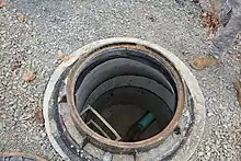
When underground sewer lines are laid close to the ground level (this may be at the depths of less than 0.75 metres (2.5 ft) or 2 metres (6.6 ft) depending on local regulations), an inspection chamber is used as an access point instead.[6][7] Inspection chambers allow access to sewer lines without requiring a person to get in them.[6]
Locations
Sanitary manholes should be constructed at locations where there is a change from a simple straight sewer line. These include all junctions that combine multiple lines into one or split from one, bends, changing in elevation, changing in pipe size, and changing in pipe type.[5]
For straight sewer lines, there is no universal agreement on spacing requirements of sanitary manholes for such lines. Historically, in business cores of urban areas in the United States, manholes may be placed at each and every street block, 300 to 400 feet (91 to 122 m) apart.[8] A more modern guideline in the United States suggested to have them every 400 feet (120 m) for small diameter sewers, and every 500 feet (150 m) for larger sewer mains.[5] Similar spacing guidelines of 120 m and 150 m can be seen in Canada with specificities on sewer diameters.[9] England sets maximum spacing at 90 metres (300 ft). The only exception is for sewers with diameters larger than human heights. Those can have spacing up to 200 metres (660 ft).[10] Maximum spacing of 100 metres (330 ft) is used in Scotland.[11] The 120-metre (390 ft) requirement is used in Brazil,[12] and 150-metre (490 ft) in South Africa.[13]
Construction
Historically, sanitary manholes were built in one piece by bricks. A large circular concrete was built at the bottom to form smooth channels for sewage to pass through. Brick wall was laid to raise up to be closer to the ground level. In this section, the wall diameters could be gradually smaller. Near the top, the brick wall diameters were rapidly reduced, forming a cone shape to meet a smaller diameter cover. A ladder of iron rungs was built on to the wall.[8]
Modern sanitary manholes have five main sections from the bottom to the top. The base section is where the channels are located. The barrel section, also known as chamber, sits on top of the base. It is a straight section instead of being gradually narrower like in older manholes. The heights of this section vary depending on the depths of the manholes. Near the top is the cone section where it reduces from the size of the chamber to the size of the cover. Chimney section, also known as shaft, is a straight and narrow section that sits on top of the cone section but below the cover. The last is the cover section.[14][15][16]
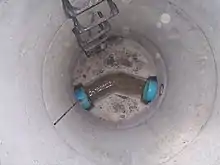
A main component of the base section is a channel that provides a smooth conduit for wastewater to flow from inlet pipe to outlet pipe. The channel is in a U shape formed by a "half pipe" as if a pipe is cut in half and left with the bottom half. The width of the channel should match the inside diameter of the inlet and outlet pipes. The lowest point of the channel is called the invert. The invert should have a slope to allow wastewater to pass through easily. The channels should be straight between the inlet and the outlet. If a direction change is needed, a channel should be continuously curved instead of having sharp corners. When joining from multiple inlets, the joint should provide a smooth transition with curves. The surface area from the manhole wall to the top of the channel is a bench. The bench should have a slope to direct water back down to the channel. The bench can be in one of the two configurations based on the lowest point of the bench that meets the channel. If the depth of the channel from the that point to the invert is half of the channel's width, it is a half bench. If the depth is the channel's width, it is a full bench. In the full bench configuration, the point from lowest part of the bench (the top of the channel) to the point that the channel shape is changed to form a U shape is a straight drop. Designing and constructing the channel and the bench should be done in high quality to reduce scouring which is a result of abrasive solids in wastewater that pass through with high velocities causing scour abrasion to degrade invert materials.[17]
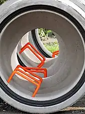
The chamber section can be built in various materials. In the 19th century, manholes in the United States were built with bricks and mortar or stone. In the mid-20th century, precast concrete was introduced. In the late-20th century cast-in-place concrete was used. Newer materials such as HDPE, concrete with corrosion reducing additives and plastics are used.[16] Currently, precast concrete is the most common material for new manholes, but bricks and concrete blocks are still used in special situations such as when the work sites are in small area which are unsuitable for precast concrete lifting operations, or for chemical waste lines.[14] When constructing sanitary manholes with precast concrete, the joints that connect between precast concrete pieces should have gaskets. The construction methods, materials should conform to precast concrete manhole standards such as ASTM C478.[18]
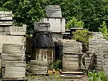
The purpose of the cone section is to reduce the openings from large chamber sizes to small cover sizes. In a masonry manhole, the bricks form a corbel inward to reduce the opening to a desired size.[14] In precast concrete, the cone section comes in two forms, concentric and eccentric. In a concentric cone section, the top opening is in the middle of the manhole. An eccentric cone has the top opening shifted off center all the way to one side of the manhole wall. This is to allow installing permanent ladder rungs on to the manhole wall. In designing eccentric cones, the loads need to be carefully calculated as one wall is vertical wall that is aligned to the chamber wall but the opposite wall is a slope.[19] Some local regulations allow reinforced concrete slabs with a smaller opening to be used instead.[15]
The chimney section sits on top of the cone section with a smaller opening to support the frame of the cover. The section can be built with the same methods and materials as in the chamber section. The heights of the chimney can vary and as they are used to make the manhole cover to flush with the ground.[15] Grade adjustment rings can also be used on top of a cone section instead of the chimney section to adjust the frame to the required level.[20]
The cover section is the top most section of sanitary manholes. It consists of a frame and a manhole cover.[16] The covers are designed to withstand the loads of the traffic on top of the manholes. Some are suitable for vehicular traffic, and some are for foot traffic only.[7]
Doghouse manholes
.jpg.webp)
A common method to add a new lateral pipe to an existing sewer line without any service interruption is to use a doghouse manhole. A special precast concrete structure has two upside-down U shape openings at the bottom directly opposite of each other. It also has a hole at a higher point for a new pipe to be inserted in. To install this, the doghouse manhole is lowered to have the two openings to slide over the existing pipe. The concrete is poured in to form the base with slopes from the precast concrete wall down to the half point of the existing pipe. This forms a half bench for the manhole base. The top half of that existing pipe is cut open to form a channel. A new pipe is inserted through the wall hole. This will allow wastewater from the new pipe to drop onto the bench and slide down to the channel. The upper portion of the manhole is built on top of that section.[21]
Floodplain manholes
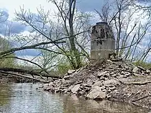
Sanitary manholes located in wetlands, salt marshes, or floodplains are susceptible to inflow issues. These are when outside water coming in directly to sewers through manhole covers.[22] Floodplain manholes should be elevated to have their rim of the top frame above the maximum flood level to prevent the inflow.[23] When that is not possible, any manhole covers that are subject to standing water should be completely sealed. Pick holes of the covers should be plugged with small balls. Plastic or stainless steel bowls can be used to insert between the cover and the frame to prevent inflow to get down to the chamber.[5] Liners can be placed outside of floodplain manholes to reduce the inflow.[24]
When running a sewer line under a river that is prone to flooding, the heights of the elevated manholes must be higher than the maximum flood level. The elevated manholes can be higher than river banks and sometimes can be taller than human. Large and tall structures of floodplain manholes are visible to people and could cause people to wonder.[25]
Types by function
Junction manholes

At any junction of more than one sewer, there should be a junction manhole. There are general rules that should be followed to avoid overflow. The inverts of the smaller sewers should be curved into the main sewer channel. Inside diameter of smaller inlets should be above the invert of the main sewer. However, that should not be too high off the main sewer channel.[1]
Drop manholes
Wastewater contains a mixture of liquid and solids. Dropping solids down from an inlet pipe at a higher elevation may cause some residual not to go down the manhole channel and the outlet pipe. This can also damage the manhole. Therefore, elevation difference between the inlet pipes and outlet pipe should not be too high, for example, less than 60 centimetres (24 in).[1]
There are two methods to avoid this problem. The first method is to make the inlet sewer pipe inclined from the previous manhole. This will allow the elevation of the inlet sewer to be lower and closer to the manhole channel. A disadvantage of this method is a requirement to have deep trenching to lay the inclined pipe which may not be practical. When using this method for larger sewers (diameters larger than 45 centimetres (18 in)), additional steps are needed in order to minimize turbulence of the steep flow of larger inlet sewers by slowing the flow down. Those include creating raised structure to break up the flow.[1]
The second method is to use a drop manhole. A drop manhole is a junction manhole that is equipped with a structure to allow liquid and solids in the wastewater to smoothly drop down to the channel inside the manhole. There are two types of drop manholes, vortex and plunging drop manholes.[26]
In a vortex drop manhole, the flow from a higher elevation enters a vertical shaft that has a spiral structure. The flow spirals down the shaft to a lower elevation at the base of the manhole. While the flow travels down the structure, it clings against the outer wall of the spiral structure. The friction of such interaction causes the flow energy to be dissipated, resulting in the speeds of the flow to be under control.[26][27]
In a plunging drop manhole, a vertical pipe is used to allow the flow from a higher elevation to drop down directly to the manhole base within that vertical pipe.[26] The vertical pipe of a plunging drop manhole (known as a drop pipe) can be configured in two ways. One way is to have the drop pipe inside the manhole. The other way is to have the drop pipe outside but next to the manhole. For outside drop pipes, there should be a clean out pipe connecting back to the manhole wall to allow inspection to upstream sewer from inside the manhole.[1]
Side entrance manholes
In case that there are other utilities laid over the sewer line at the location that requires a sanitary manhole, an alternative is to build a side entrance manholes. The vertical shaft of a side entrance manhole is located at a location that does not have an obstacle. At the bottom of the manhole, there is a tunnel to connect to the sewer line laterally to allow sanitary workers to access the sewer.[1]
Scraper manholes
In larger sewers that require regular cleaning by scrapers, the access to such sewers must be through manholes with larger openings to allow cleaning equipment to be lowered. Scrapper manhole openings are with sizes between 90 and 120 centimetres (3.0 and 3.9 ft).[28] An alternative to having people to go down scraper manholes to remove sewer blockage is to use jet rodders and vacuum trucks. Those can be operated from the ground level though normal size manholes[1]
Flushing manholes
At the head of a sewer, there can be little flow that can be used to move solids in wastewater down the sewer. Additional flow may be required to flush out those deposits. This can be accomplished by having a flushing manhole at the head sewer. Flushing manholes are used to store water that can be released to flush solids in the sewers. A simple design is a manhole that allows a sanitary worker to open and close a value from the ground level to perform water filling and flushing operations. Water source for flushing manholes can come from potable water, tidal water, or water from clarifiers of sewage treatment plants[1][29]
Maintenance and issues
Infiltration and inflow

Infiltration and inflow (I&I) occurs when water other than wastewater enters sewer system. Infiltration is when water from the ground enters sewers through defective pipes, joints, and manholes. All sewer pipes and sanitary manholes should be sealed to prevent ground water to leak into sewer system. Inflow enters directly through opening parts of the sewer system such as vents and manhole covers. In normal operations, small amounts of infiltration and inflow are expected. When those amounts are excessive, they could cause sewer system to have surcharges, higher operational costs to transport and treat higher than design wastewater volumes, or sanitary sewer overflow.[30]
A preventative measure is to regularly test sewers and manholes. A few methods have been used to perform I&I tests. Historically, water testing was used. This can be an infiltration or exfiltration test which would block a certain section of sewers for a duration of a test, typically 24 hours. Infiltration testing is to use a weir as a device for flow measurement. The measurement showed the amount of infiltration and inflow in the system. Exfiltration testing uses water to fill up a manhole and measurements are taken to detect leaks. In a modern time, vacuum testing is performed to check integrity of manholes and identify for leaks.[31] Another common testing method is smoke testing. In this method, sandbags are used to seal a sewer section, then smoke is pumped into a manhole. Any leaks can be observed by visible smoke at the areas of the leaks.[32]
Rainfalls can induce excessive infiltration and inflow.[30] When that starts to create a sanitary sewer overflow, and immediate action is required. One method is to use pumps to take water of affected manholes. Given that rain water is mixed with wastewater, the pumped water needs to be contained and transported to a sewage treatment plant.[33]
Sanitary sewer overflow

Sanitary sewer overflow is a condition in which untreated sewage is discharged from a sanitary sewer into the environment prior to reaching sewage treatment facilities. Manholes are common locations of sanitary sewer overflows. The causes of overflows may be from excessive infiltration and inflow, or blockages. In case of a blockage, manholes need to be inspected. Typically, the blockage happens between the manhole with an overflow and the next downstream manhole. A downstream manhole with less than expected inlet flow or dry indicates a blockage upstream of it. To solve a blockage, a sand trap is placed in the channel at the outlet of the downstream manhole in order to catch any debris while allowing water to go over it to the outlet pipe. Then a jet flushing or power rodding is used to clan from the outlet pipe of the upstream manhole in an attempt to dislodge the blockage which will be caught at the sand trap of the downstream manhole.[34]
Uplifted manholes
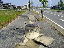
Many manholes may appeared to be uplifted from the ground after an earthquake. This damages sewer infrastructure, creates road obstacles, and prolongs a disaster recovery process. There are two causes of uplifted manholes.[35]
The first cause is soil liquefaction. Saturated loose soils can loses strength and stiffness in response to an applied stress such as shaking during an earthquake. The soils cannot drain pore water fast enough in a repeated compression causing the pore water pressure to be accumulated to a high pressure. This causes the soils to lose their stress and become muddy. Any objects with apparent weights of less than of those of the ground's muddy water will float up. Manholes, which are sealed hollowed objects with lower apparent weights, will be forced to push upward after a soil liquefaction. A solution to prevent manholes to be uplifted is to create drain plugs throughout a manhole wall. The plugs have screens to prevent dirts but allow water to drain through. The pressure-sensitive plugs are calibrated to hold water up to a certain pressure level which is higher than normal ground water pressure. Once the pore water pressure is increased to higher than that level due to an earthquake, the plugs will be released into the manhole and the water from the surrounding soils can be drained into the manhole, preventing soil liquefaction.[35]
The second cause is broken seals at the manhole joints due shifting of the ground causing an inflow of the sediments surrounding the manholes to enter through the joints. This results in sunken roads and the sediments fill up manholes and sewers. This is not an uplift of a manhole but rather a subsidence of an area next to a manhole. A solution to this to have a flexible and watertight sheet attached over each joint on the inside wall of the manhole. When the ground is shifted, the sheets can still provide sealed barriers at the shifted joints, preventing inflow of the sediments.[35]
References
- "3". Manual on Sewerage and Sewage Treatment Systems Part A Engineering (PDF). Central Public Health & Environmental Engineering Organisation (CPHEEO). 2013. Retrieved 15 April 2023.
- "Oregon Standard Drawings: Standard Sanitary Sewer Manhole" (PDF). Oregon Department of Transportation. Retrieved 14 April 2023.
- "Construction Specifications and Drawings for Sewers and Watermains". City of Toronto. 17 November 2017. Retrieved 14 April 2023.
- Hillhouse, Grady (2023). Engineering in plain sight : an illustrated field guide to the constructed environment. San Francisco, CA. pp. 186–188. ISBN 9781718502338. Retrieved 14 April 2023.
{{cite book}}: CS1 maint: location missing publisher (link) - Parcher, Michael J. (1998). Wastewater collection system maintenance. Lancaster, PA. p. 241–243, 249. ISBN 9781566765695. Retrieved 15 April 2023.
{{cite book}}: CS1 maint: location missing publisher (link) - South African Bureau of Standards Code of Practice for the Application of the National Building Regulations (PDF). The Council of the South African Bureau of Standards. p. 15. Retrieved 15 April 2023.
- Your new sewer construction guide (PDF). Thames water. May 2021. pp. 4–5. Retrieved 15 April 2023.
- Cyclopedia of Civil Engineering: A General Reference Work on Surveying, Railroad Engineering, Structural Engineering, Roofs and Bridges, Masonry and Reinforced Concrete, Highway Construction, Hydraulic Engineering, Irrigation, River and Harbor Improvement, Municipal Engineering, Cost Analysis, Etc, Volume 7. American school of correspondence. 1909. pp. 254–255. Retrieved 15 April 2023.
- Design guidelines for sewage works (PDF). Ontario, Ministry of the Environment. 2008. p. 5-26. ISBN 978-1-4249-8438-1. Retrieved 15 April 2023.
- "Part H". The Building Regulations 2010: Drainage and waste disposal (PDF) (2015 ed.). HM Government. p. 23. Retrieved 15 April 2023.
- Sewers for Scotland - A technical specification for the design and construction of sewerage infrastructure (PDF) (Version 4.0 ed.). Scottish Water. October 2018. p. 61. Retrieved 15 April 2023.
- "7". The Study on Management and Improvement of the Environmental Conditions of Guanbara Bay in Rio de Janeiro, The Federative Republic of Brazil (PDF). Japan International Cooperation Agency. October 2003. p. 7-7. Retrieved 15 April 2023.
- Van Vuuren, S. J. (2011). Waterborne sanitation design guide : report to the Water Research Commission (PDF). Gezina [South Africa]: Water Research Commission. p. 87. ISBN 978-1-4312-0078-8. Retrieved 15 April 2023.
- Beall, Christine. "Brick and concrete masonry manholes". The Aberdeen Group. Retrieved 22 April 2023.
- Typical Manhole Details (PDF) (Technical report). Yorkshire Water. April 2020. YW-DS-001. Retrieved 23 April 2023.
- Pollak, Denis (1 August 2009). "Manhole Inspection Key to Collection System Performance". WaterWorld. Retrieved 23 April 2023.
- Manhole Invert Channels: An Overview (PDF) (Technical report). National Precast Concrete Association. March 2013. Retrieved 22 April 2023.
- "ASTM Manhole Specifications". Precast Magazines. No. September-October 2011. 26 September 2011. Retrieved 23 April 2023.
- Carleton, Eric (1 April 2015). "Speaking in Cone". Precast Magazines. No. Spring 2015. Retrieved 23 April 2023.
- "What Happens After You Flush - Manholes". Louisville/Jefferson County Metropolitan Sewer District. Retrieved 23 April 2023.
- Munkelt, Gary K. (12 December 2012). "Precaster's Notebook: Anatomy of a Doghouse Manhole". Precast Solutions Magazine. No. Winter 2012. Retrieved 26 April 2023.
- "Community Support Program Infiltration/Inflow Local Financial Assistance". Massachusetts Water Resources Authority. Retrieved 15 April 2023.
- "Installation Detail - Raising Maintenance Hole Within a Flood Plane" (PDF). City of Toronto. Retrieved 16 April 2023.
- Water Compliance Inspection Report WA-0022608 (Report). State of Washington Department of Ecology Eastern Regional Office. 23 January 2018. Retrieved 16 April 2023.
- Moore, Eva (25 October 2017). "Burning Questions: What are Those Stinky Concrete Mounds Along the Riverwalk?". freetimes. Retrieved 16 April 2023.
- "Drop Manhole". Trenchlesspedia. Retrieved 6 May 2023.
- Crispino, Gaetano; Contestabile, Pasquale; Vicinanza, Diego; Gisonni, Corrado (12 January 2021). "Energy Head Dissipation and Flow Pressures in Vortex Drop Shafts". Water. 13 (2): 165. doi:10.3390/w13020165.
- Final Report on Water Quality Management Plan for Ganga River Volume IV-1, Feasibility Study for Lucknow City, Part I, Sewerage Scheme (PDF). Japan International Corporation Agency. July 2005. p. 3-3. Retrieved 18 April 2023.
- "Flushing Manholes". FWPCOA. Retrieved 8 May 2023.
- Guide for Estimating Infiltration and Inflow (PDF) (Technical report). U.S. EPA New England. June 2014. Retrieved 8 May 2023.
- Lawrence, Greg (2 April 2018). "Preventing Infiltration and Inflow". Waste Water Digest. Retrieved 8 May 2023.
- "Smoke Testing 101: An Introduction to Smoke Testing". Water Technology. 1 April 2002. Retrieved 8 May 2023.
- "Clean-Up Continues After Hambledon Flooding". Capital FM. 21 January 2014. Retrieved 8 May 2023.
- Optimizing Operation, Maintenance, and Rehabilitation of Sanitary Sewer Collection Systems (PDF). New England Interstate Water Pollution Control Commission. December 2003. p. C-17. Retrieved 8 May 2023.
- Yukihiro, Ishikawa (1 January 2012). "Technology Development of Anti-seismic Structures for Sewer Networks" (PDF). Proceedings of the Water Environment Federation. 2012 (13): 2911–2923. doi:10.2175/193864712811726662. Retrieved 9 May 2023.