1

I am using the power MOSFET IRF504N. I am not sure if my Rpi's GPIO 3V3 signal can directly input to the gate of the MOSFET which requires 4V minimum.

I guess that I don't need a gate driver to shift up the Rpi's 3V3 signal. So I am now experimenting, ...


I read the IRF540N datasheet which says Vgs(th) is 2V minimum and 4V maximum. Does it mean Vgs between 2V to 4V won't guarantee anything?


I forgot to mention that the motor is DC12V 100mA (37GB528-70 70rpm). And I also want to drive another solenoid valve DC12V 300mA (FDZ-5). The picture below shows the two little guys.

Motor and Solenoid Valve Picture

schematic

simulate this circuit – Schematic created using CircuitLab
tlfong01
  • 4,384
  • 3
  • 9
  • 23
  • 1
    For future reference any edits to a question can be made using the edit button at the bottom of the question. Edits to the question, (including adding additional information) should not be posted as answers. – Darth Vader Feb 09 '19 at 10:21
  • Many thanks for your advice and help on how to edit the question.. – tlfong01 Feb 09 '19 at 14:37
  • You should add a current limiting resistor and a pull down resistor on the MOSFET gate. – MatsK Feb 09 '19 at 16:53
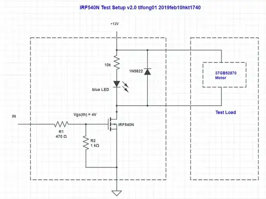
  • Many thanks for your advice. I googled and found that the current limiting series resistor could be 330 to 470R, and gate pull down resistor 1k to 2k. The EE StackExchange I googled is: Mosfet does not turn off - 2017may30 https://electronics.stackexchange.com/questions/308054/mosfet-does-not-turn-off – tlfong01 Feb 10 '19 at 06:56

2 Answers2

2

This might work, but it won't work well.

The parameter you've asked about (Vgs(th) is 2V minimum and 4V maximum) means this:
The threshold voltage at which conduction begins from Drain to Source is a minimum of 2 V, and a maximum of 4 volts. Since the RPi GPIO is 3.3 V, there will be some devices that may not conduct at all. See Fig 3 in this spec sheet.

Bottom Line: You need to drive your chosen MOSFET with a much higher voltage than the 3.3 V available from the RPi GPIO pin if you want your circuit to operate "properly" (within design specifications). You should have around 7 V gate-source voltage for best results - at least for this MOSFET.

Seamus
  • 18,728
  • 2
  • 27
  • 57
  • I am confused. I don't understand why you say Rpi GPIO is 3V6. – tlfong01 Feb 11 '19 at 01:53
  • @tlfong01: It was an error... thank you for catching it. I've corrected my post. – Seamus Feb 11 '19 at 07:37
  • I neither understand why it is 7V and not 5V or 9V. Does this magic number 7 applies to all loading? – tlfong01 Feb 12 '19 at 05:17
  • You need enough G-S voltage to form the D-S channel *AND* drive the channel resistance down to a "low" value. The G-S voltage should be "well above" the *threshold voltage* (up to 4 V), and "well below" the maximum rating (20 V). I chose 7 as a reasonable value. You can use anything you like between the threshold and the max. Go for it. You can actually learn quite a lot by reading the spec sheets, tutorials and studying the application notes that most mfrs publish. – Seamus Feb 12 '19 at 09:52
  • Well, I did read the tutorials and application notes before studying the datasheet. Fig 3 of the datasheet https://penzu.com/p/f445eb50 seems to say that for Vgs = 5V, the channel opens wide enough to let 20A pass through. So I don't understand why Vgs 5V cannot do for less current. I already have a level shifter converting Rpi GPIO 3V3 signal to 5V, so I wish to know if 5V will do as good as 7V, for my 35mA motor, and my original question is if direct Rpi GPIO 3V3 signal without level shifting can also do for such small loading. – tlfong01 Feb 13 '19 at 07:40
  • I found the following post answers my question well. Using MOSFETS with TTL levels (5 Volt and 3.3 Volt) - May 2, 2012 https://arduinodiy.wordpress.com/2012/05/02/using-mosfets-with-ttl-levels/ – tlfong01 Feb 18 '19 at 11:53
  • However, the above 2012 post is a bit out of date, and does not discuss the IRF540N which I am asking. Luckily I found another post which is as good, and specifically discussing IRF540: "Controlling a 5V Solenoid with a Mosfet irf540 - electroturk 2013oct13 (Read 12326 times)" https://forum.arduino.cc/index.php?topic=193119.0 – tlfong01 Feb 20 '19 at 03:17
0

OP asks if Rpi 3V GPIO signal can trigger the N-channel power MOSFET IRF540N with trigger threshold >4V to drive (a) 12VDC 35mA motor, (b) 12VDC 250mA solenoid.

A short answer is that RPi's 3V GIPO high signal can likely trigger and slightly turn on the IRF540N's channel to barely pass through <50mA and therefore can slowly move a 35mA DC motor. However the barely opened channel with high Rds on resistance does not allow enough current to drive a >100mA solenoid.

There is a get around - use a 3V/5V logical level trigger alternative such as IRL540N.

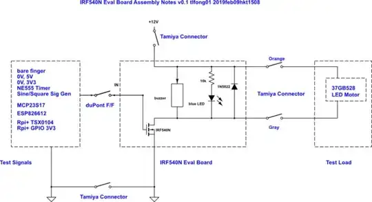
Rpi 3V GPIO triggers IRF540N to drive 35mA DC motor

References

(1) AN11158 Application Note Understanding power MOSFET data sheet parameters - Rev. 6.0 — 2020jul06

tlfong01
  • 4,384
  • 3
  • 9
  • 23
  • ***IRF540N*** was used in this test, because it was popular and I had plenty in hand. The bad thing about IRF540N it that its gate triggering threshold voltage > 4V is too high for Rpi, whose logical High voltage is only around 3V. For Rpi newbies, I would recommend to use ***IRL540N*** instead. – tlfong01 Jun 04 '22 at 02:52