This article was co-authored by wikiHow Staff. Our trained team of editors and researchers validate articles for accuracy and comprehensiveness. wikiHow's Content Management Team carefully monitors the work from our editorial staff to ensure that each article is backed by trusted research and meets our high quality standards.
There are 9 references cited in this article, which can be found at the bottom of the page.
This article has been viewed 34,394 times.
Learn more...
A transistor is an electrical device which can amplify and boost an electrical current. Transistors can also function as switches and turn different electrical currents on and off. To see how transistors work, you can use one to construct and operate a simple electrical switch. You can easily find all the materials you'll need at an electronics supply store.
Steps
Inserting the Transistor and Resistors
-
1Purchase a BJT transistor, a breadboard, resistors, and other supplies. Visit a local electronics store to pick up the items you’ll need to construct a simple circuit. Buy a solderless breadboard with 830 tie-points and 1 LED lightbulb. Find the 470Ω resistors, and purchase a small box (you’ll only need 2 individual resistors). Also, pick up a reel of solid copper hookup wire. Finally, purchase a 9-volt battery.[1]
- There are many different types of transistors, and the Bipolar Junction Transistor (BJT) is one of the most popular styles. It’s also fairly straightforward to use and is a good option for anyone new to working with transistors. A BJT transistor works by receiving a small electrical current and converting it into a much larger current.[2]
-
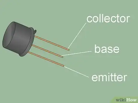
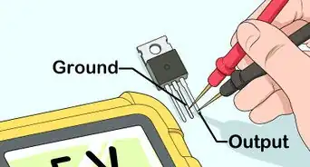
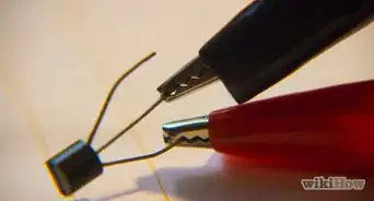
2Identify the pins on your transistor. Your BJT transistor will have a plastic head with 3 small metal pins sticking out of 1 end. Hold the transistor so that the front side (with writing on it) is facing you. With the transistor in this position, the leftmost pin is the emitter, the central pin is the base, and the rightmost pin is the collector.[3]
- These 3 pins each serve a different function, so it’s important to correctly identify them.
Advertisement -
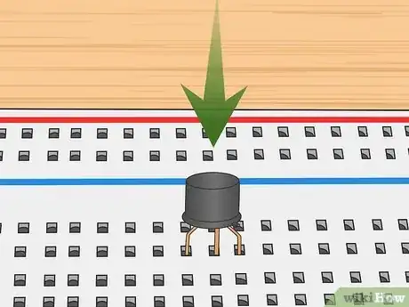
3Stick the transistor into the breadboard. With the front of the transistor still facing towards you, insert each of the 3 metal pins into a separate hole in the breadboard. Choose 3 adjacent holes in any part of the breadboard. Insert the emitter to the leftmost hole, the base to the central hole, and the collector into the rightmost of these 3 holes.[4]
- This may take some delicate work since each of the breadboard holes is only about 1⁄32 inch (0.79 mm) across.
- A breadboard is a roughly 10 in × 6 in (25 cm × 15 cm) piece of plastic with electrical wiring running between the individual holes. It’s commonly used in electrical experiments with transistors since electrical power will run between any metal elements connected to the breadboard.
-
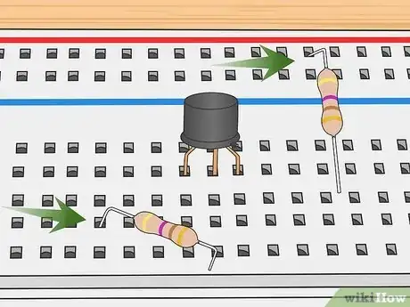
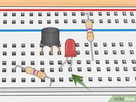
4Insert the two 470Ω resistors into breadboard holes near the transistor. Each of the resistors comprises a thick, plastic-covered bar with a thin wire extending from both ends. Bend these wires until they’re at a 90-degree angle from the body of the resistor. Then, insert the wires into holes in the breadboard. Due to the resistors’ size, the holes should be about 6 apart from one another by both width and length.[5]
- Insert the first resistor on the upper-right hand side of the transistor within 2-3 holes of those the transistor is in. Then, place the second resistor on the lower-left side of the transistor, also within 2-3 holes of the transistor's location.
- Resistors help slow down and re-direct the flow of electric current. They’re used in simple circuits to prevent the wiring and LED bulb from overheating. Resistors look like a 2 in (5.1 cm) piece of wire with a 1 in (2.5 cm) plastic tube wrapped around the middle.[6]
Connecting the LED Bulb
-
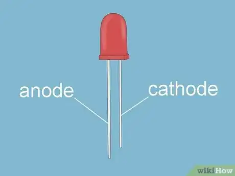
1Identify the leads on the LED bulb. A standard LED bulb comprises the bulb itself and 2 leads (thin wire filaments). One of the leads is the cathode and the other is the anode. Identify the cathode by finding the shortest lead. The anode, then, is the longer lead. Also inspect the surface of the bulb itself and see if it provides an indication as to which is which.[7]
- When you’re connecting the LED, always connect the anode to the circuit’s positive side. If you mistakenly connect the anode to the circuit's negative side, the circuit won't work and the LED won't light up.
- LED bulbs burn brightly when powered with only a small amount of electric current.
-
2Insert the LED bulb and connect it to the transistor. The LED must be directly to the right of the transistor for the circuit to function. Stick the 2 leads in through 2 adjacent holes in the breadboard. Then, connect the cathode lead to the transistor’s collector pin.[8]
- To connect the cathode lead to the transistor pin, simply twist the 2 wires together under the breadboard. Make 2-3 twists to ensure that electricity can flow between the wires.
-
3Connect 1 resistor to the LED. Connect the first resistor that you inserted to the positive (red) power rail running alongside the nearest long edge of the breadboard. Attach the first resistor’s second wire to the anode of the LED. Connect the second resistor that you inserted to the base (central pin) of the transistor.[9]
- Make the connection sturdy by bending the resistor wires 2-3 times around the wires you connect them to.
Wiring the Transistor Circuit
-
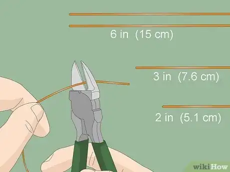
1Cut 4 sections of wire from a reel of hookup wire. You’ll need these wire segments to connect the parts of your circuit. Use a pair of wire cutters to snip a 3 in (7.6 cm) section of wire. Then, cut 2 more segments, each about 6 in (15 cm) long. Finally, cut 1 short 2 in (5.1 cm) long segment of wire.[10]
- If you don’t have wire cutters, purchase a pair at a local hardware or electronic-supply store.
-
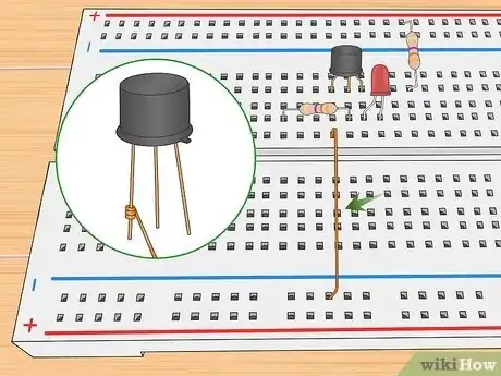
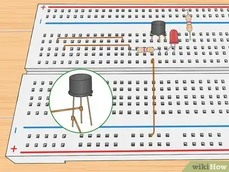
2Ground the emitter to the negative power rail. To function, your circuit will need to be grounded. Poke 1 end of the wire through a breadboard hole near your transistor and wrap it around the emitter wire 2-3 times. Then, stick the other end of the wire in a breadboard hole connected to the negative power rail.[11]
- Identify the negative power edge of the breadboard by visually inspecting it. Both of the 2 long edges of the breadboard will have both a negative and positive rail. The negative rail will always be accompanied by a “–” sign and will be blue or black.[12]
-
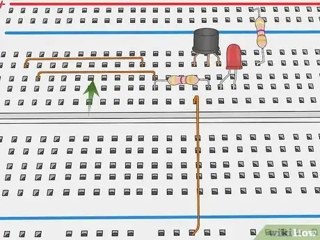
3Insert both 6 in (15 cm) wire segments into the breadboard. Bend the last 1⁄2 inch (1.3 cm) of the 2 long wire segments so it’s at a 90-degree angle to the rest of the wire. Insert 1 end of both wires in breadboard holes near the transistor. Insert the other end of both long wire segments into holes at the far end of the breadboard.[13]
- Choose holes in the same row so that the 2 long wires are parallel to one another.
- Due to the wire segments length, the 2 ends of each segment will be inserted roughly 25 holes apart.
-
4Connect 1 of the long wires to the transistor. Find the long wire nearest the base of the transistor. Beneath the breadboard, wrap the wire’s end 2-3 around the transistor’s base (the central pin).[14]
- If the wires are too short or too stiff to bend with your fingers, use a pair of needle-nose pliers to bend the wires.
-
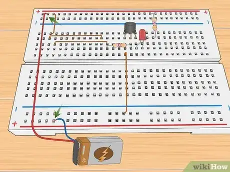
5Attach the second long wire to the positive rail. Wrap 1 end of your short 2 in (5.1 cm) segment of wire 2-3 times around the end of the second long wire (that’s not connected to the transistor). Do this on the end farthest away from the transistor. Then, bend the short wire, and insert its other end through a hole in the positive (red) rail on a long edge of the breadbox.[15]
- This will allow power from the battery to get to the LED, once you’ve connected the battery.
-
6Hook the battery up to your circuit. Connect the 9-volt battery connector to the positive and negative outlet ports on the battery itself. Hook the negative (blue) wire around the negative power rail at the end of the breadboard farthest from the transistor. Connect the positive (red) wire coming from the 9-volt battery to the positive power rail.[16]
- The 9-volt adapter comprises a rubber head with 2 receivers to snap on the + and – ports of the battery. Notice that 2 wires emerge from the head: 1 positive (red) and 1 negative (blue).
-
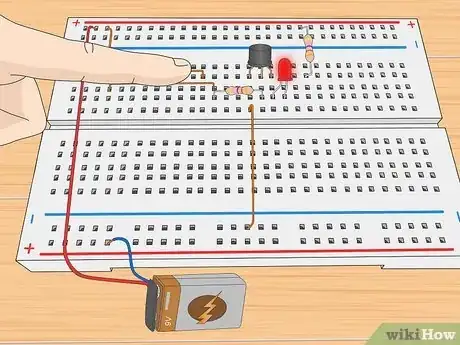
7Touch the 2 long wires to activate the circuit. These wires are referred to as the “touch wires.” Use 1 finger and press down on the 2 touch wires. Make sure that you’re touching both at once. Press them down against the breadboard, and watch as the LED lights up.[17]
- Try experimenting with different types of touch: light, heavy, etc. Depending on how much pressure you put on the wires, you’ll notice that the LED illuminates more or less brightly.
Things You’ll Need
- 1 Bipolar Junction Transmitter (BJT) transistor
- 9-volt battery
- 9-volt battery connector
- LED lightbulb
- 830 tie-point breadboard
- two 470Ω resistors
- 1 reel of copper hookup wire
- Wire cutters
- Needle-nose pliers
References
- ↑ http://homediyelectronics.com/projects/transistortouchswitchsimplescienceproject/?p=2
- ↑ https://www.elprocus.com/different-types-of-transistor-and-their-functions/
- ↑ https://www.elprocus.com/easy-pin-identification/
- ↑ http://homediyelectronics.com/projects/transistortouchswitchsimplescienceproject/?p=3
- ↑ https://youtu.be/-yLAboW_E3s?t=75
- ↑ https://www.build-electronic-circuits.com/what-is-a-resistor/
- ↑ http://homediyelectronics.com/projects/transistortouchswitchsimplescienceproject/?p=3
- ↑ http://homediyelectronics.com/projects/transistortouchswitchsimplescienceproject/?p=3
- ↑ http://homediyelectronics.com/projects/transistortouchswitchsimplescienceproject/?p=3
- ↑ http://homediyelectronics.com/projects/transistortouchswitchsimplescienceproject/?p=3
- ↑ http://homediyelectronics.com/projects/transistortouchswitchsimplescienceproject/?p=3
- ↑ https://www.sciencebuddies.org/science-fair-projects/references/how-to-use-a-breadboard
- ↑ http://homediyelectronics.com/projects/transistortouchswitchsimplescienceproject/?p=3
- ↑ http://homediyelectronics.com/projects/transistortouchswitchsimplescienceproject/?p=3
- ↑ http://homediyelectronics.com/projects/transistortouchswitchsimplescienceproject/?p=3
- ↑ http://homediyelectronics.com/projects/transistortouchswitchsimplescienceproject/?p=3
- ↑ https://youtu.be/-yLAboW_E3s?t=31
- ↑ https://www.explainthatstuff.com/howtransistorswork.html

