This article was co-authored by Ralph Childers and by wikiHow staff writer, Christopher M. Osborne, PhD. Ralph Childers is a master electrician based in the Portland, Oregon area with over 30 years of conducting and teaching electrical work. Ralph received his B.S. in Electrical Engineering from the University of Louisiana at Lafayette and holds an Oregon Journeyman Electrical License as well as electrician licenses in Louisiana and Texas.
This article has been viewed 53,404 times.
Whether you want to test a simple circuit you’ve made for a school project or a wall outlet in your home, there are several testing tools you can use to check for continuity—that is, a completed circuit. A continuity tester is the simplest tool for the specific task of checking for continuity, while a multimeter also provides a wide range of other electrical testing uses. You can also use a circuit tester to check for continuity, but its best use is checking for proper grounding of your circuit. Always use caution when working with live wires!
Steps
Using a Continuity Tester on Circuits
-
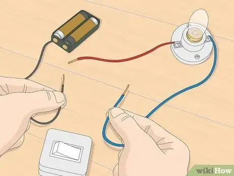
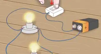
1Disconnect the power from the circuit you want to test. Continuity testers work by sending a small current through the circuit, so the circuit needs to be disconnected from its power supply. If you’re testing a simple school project circuit (two wires running between a 9v battery and a light, for instance), just disconnect the wires from the battery.
- If you’re testing for continuity in home electrical wiring, turn off the appropriate breaker at your main electrical service panel. Next, test a non-contact voltage tester on a circuit you know is working (such as any meter you use daily). Then, use the non-contact voltage tester to make sure the power is off at the circuit you’ll be testing.[1]
- Separate the circuit you want to test from other potentially hot wires to ensure you don't get a false positive. Then, simply place the tip of the voltage tester near the wiring of the circuit you’ll be testing. If the voltage tester lights up and “chirps,” the power is still on.
-
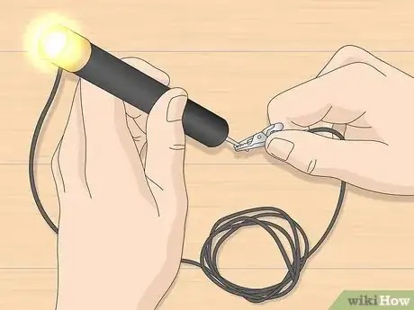
2Make sure your continuity tester works. A basic continuity tester, which you can buy at any hardware store, consists of a small cylinder with a lamp at one end and a probe at the other. A battery goes inside the cylinder to power the tester, and a flexible wire with a clip extends out from the cylinder.[2]
- To test that it’s working, simply touch the clip to the probe. If the lamp comes on, it’s working. If it doesn’t, check the battery.
- Continuity testers are cheap and easy to use, but you can also find instructions online for making your own with a few simple parts.
Advertisement -
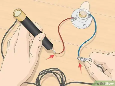
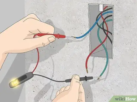
3Touch the probe and attach the clip to opposite ends of the circuit. For the basic “2 wires running from a 9v battery to a light” circuit setup, attach the clip to one of the wires you disconnected from the battery, and touch the probe to the other detached wire. It doesn’t matter which wires you clip or touch.[3]
- If you’re trying to figure out which wire connects to which between a wall switch and nearby wall outlet at home, take the cover plates off and unbundle or detach the wire ends—but only after you’ve confirmed with a voltage tester that the power is off. Attach the tester’s clip to a wire at one box, then start touching the probe to wires in the other box.[4]
-
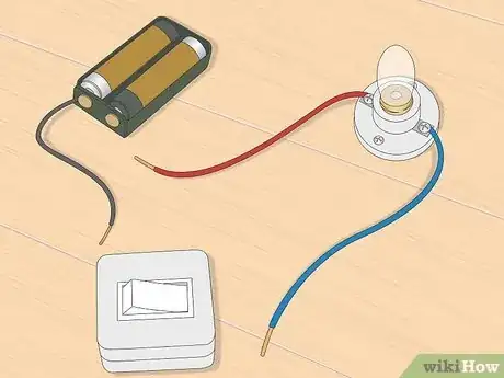
4Watch for the lamp to illuminate on your tester. If the lamp lights up, you have a completed circuit. If it doesn’t—and you’ve already made sure the tester’s battery is working—then you don’t have a completed circuit.
Testing Continuity with a Multimeter
-
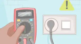
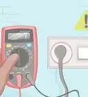
1Remove all current from the circuit you’re testing. Either disconnect your simple circuit from its battery or shut off your home circuit’s power supply at the breaker box. For home wiring in particular, always ensure that the power is actually off by using a non-contact voltage tester.[5]
- Non-contact voltage testers look like thick pens and can be found at any hardware store. They light up and make a chirping sound whenever the probe end is placed in close proximity to an electrical current.
- When using a non-contact circuit tester, make sure to separate the wires you want to test from all nearby wires. If the wires are too close, a hot wire's magnetic field can affect the reading and show a false positive.
-
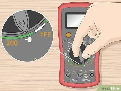
2Turn your multimeter’s dial to continuity mode. Multimeters vary by make and model, but nearly all of them have a dial on the receiver with an array of settings. If your multimeter has a continuity setting, it will usually be denoted by an image of a series of curved lines that look like a sound wave.[6]
- Typically, the symbol will look something like this— ))))) —except that the curved lines will go from smaller to larger from left to right.
- Read the manual that came with your meter before using it to ensure you know how to use it correctly.
-
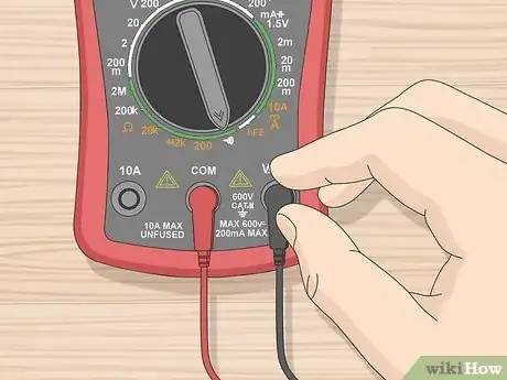
3Place the test leads into their appropriate jacks. Multimeters come with two wire leads—a black one and a red one—with plugs at one end and probes at the other. Many multimeters have at least 3 jacks in which you can plug in the leads, however, so you need to insert them properly in order to test for continuity.
- Plug the black test lead into the “COM” (or similar, for “common”) jack. This is always where the black lead goes, no matter the test you’re conducting.
- Plug the red test lead into the jack labeled “VΩ,” “VΩmA,” or similar.[7] This jack is used for low current testing, which is appropriate for circuit continuity testing. Consult your multimeter’s manual if you’re not sure which jack to use.[8]
-
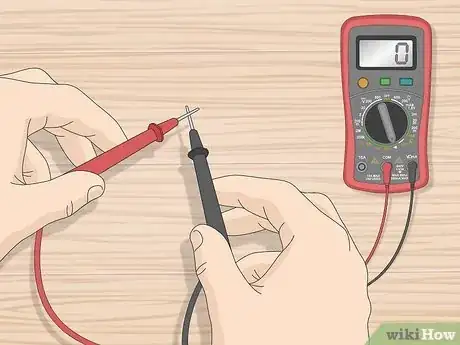
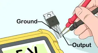
4Touch the probe ends together to test the multimeter. The multimeter tests for continuity by sending out a small current, so you’ll make a complete circuit by touching the red and black probe ends together. In most models, the multimeter will beep to indicate continuity, and may also (if it has a digital display) provide a visual indicator (such as the number 0) as well.[9]
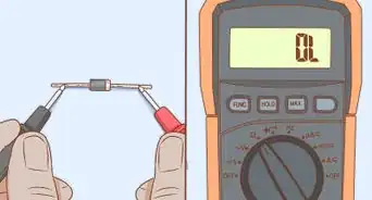
- If your multimeter doesn’t beep, and the digital display (if it has one) shows “OL” (for “open loop”) or the number 1, then it is not working properly. Check its battery and consult your user’s manual.
-
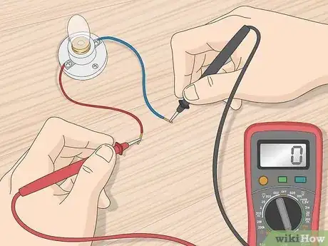
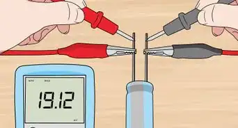
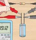
5Touch the probe ends to opposite ends of the circuit you’re testing. If you wanted to test a single strand of wire, you’d touch the probe ends to each end of the wire. If you wanted to check a small light bulb with two attached wire leads, you’d touch a probe to each of the leads. The multimeter works in this case by completing the circuit and introducing a small current into it.[10]
- Remember that, in most cases, a beeping sound and possibly a displayed “0” indicate continuity, and no beeping and possibly a “1” or “OL” indicate discontinuity.
Checking for Grounding with a Circuit Tester
-
1Rely on a circuit tester when checking older home wiring. You can use a circuit tester to confirm any type of completed circuit, but its best use is perhaps to make sure that home electrical wiring—especially in older homes—is properly grounded. You might, for instance, find a green-coated or bare copper ground wire in an outlet box, but the only way to really be sure that it is actually grounded is to test it.[11]
- If you don't have knowledge or experience working with electricity, this task is best left to a certified electrician.
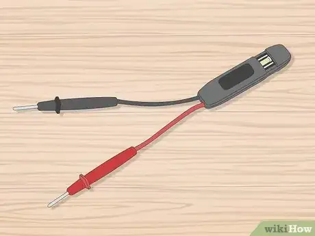
- You can buy circuit testers at any hardware store, and they look a bit like a continuity tester—a small cylinder with a light at one end (neon in this case) and two attached wires with probes (instead of one).
- Circuit testers are not-self powered, though, meaning that, unlike a continuity tester or multimeter, the circuit you’re testing needs to be supplied with power.
-
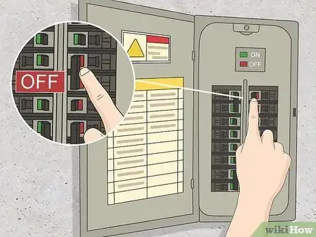
2Turn off the power supply, and confirm it’s off. If you’re checking the wiring in a wall outlet, turn off the power to that outlet at the main breaker panel. Then, place a non-contact voltage tester into the narrow slot (where you plug in) in the outlet face. If the tester doesn’t light up or chirp, the power is off.[12]
- Another way to confirm the power is off is to plug a device (that you know is working properly) into the outlet.
-
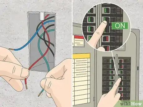
3Expose the wiring and turn the power back on. With the power confirmed off, take off the face cover and unbundle and separate the wires inside the outlet box. Make sure the exposed ends are not touching. Then, turn the power back on to the outlet at the breaker panel.[13]
- Live, exposed wires create a hazard for electrocution (if someone touches the wires) or fire (if the wires touch each other or a nearby object). Before turning the power on, make sure the exposed wire tips are completely separated and not touching anything; tell everyone in the area/home that there are live wires in that specific location; and put up a sign (e.g. "Live Wires! Don't Touch!") right near the outlet.
-
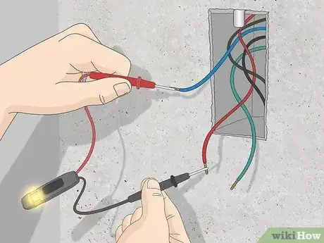
4Touch a hot wire and a neutral wire with the test probes. Touch the black probe to the exposed hot (or live) wire—it’s usually black, but could be any color other than white or green. Touch the red probe to a neutral exposed wire—which will be white. This completes the circuit, and the neon lamp should light up.[14]
- You’re testing the tester by completing this circuit. If the neon lamp doesn’t light up, either your tester is bad or the power isn’t actually back on to your outlet.
-
5Touch a hot wire and the ground wire to check for grounding. As before, touch the black probe to the exposed end of the black (or not white or green) hot wire. Then touch the red probe to the ground wire, which should either be coated in green or be unsheathed copper. If the tester lights up, you know that the outlet is properly grounded.[15]
- If the neon lamp doesn’t light up, the ground wire in this outlet box is not properly connected to the home grounding system. Call an electrician if you are not well-versed in making home electrical repairs.
- After a successful test, turn the power off at the breaker box; test the exposed wires with the voltage tester to be sure the power is off; reconnect the wires as before and close up the outlet box; and turn the power back on at the breaker box.
Warnings
- If your home is older, it may not have ground wires since they were not required by the NEC. To improve the safety of your electrical wiring, hire a professional electrician to run a ground to each device or install GFCI devices at the beginning of each circuit.⧼thumbs_response⧽
References
- ↑ https://www.familyhandyman.com/electrical/how-to-use-cheap-electrical-testers/view-all/
- ↑ https://www.familyhandyman.com/electrical/how-to-use-cheap-electrical-testers/view-all/
- ↑ https://www.familyhandyman.com/electrical/how-to-use-cheap-electrical-testers/view-all/
- ↑ https://www.familyhandyman.com/electrical/how-to-use-cheap-electrical-testers/view-all/
- ↑ https://www.ifixit.com/Guide/How+To+Use+A+Multimeter/25632
- ↑ https://www.sciencebuddies.org/science-fair-projects/references/how-to-use-a-multimeter#multimeteroverview
- ↑ https://www.ifixit.com/Guide/How+To+Use+A+Multimeter/25632
- ↑ http://en-us.fluke.com/training/training-library/test-tools/digital-multimeters/how-to-test-for-continuity-with-a-digital-multimeter.html
- ↑ https://www.ifixit.com/Guide/How+To+Use+A+Multimeter/25632
- ↑ https://www.sciencebuddies.org/science-fair-projects/references/how-to-use-a-multimeter#multimeteroverview
- ↑ https://www.familyhandyman.com/electrical/how-to-use-cheap-electrical-testers/view-all/
- ↑ https://www.familyhandyman.com/electrical/how-to-use-cheap-electrical-testers/view-all/
- ↑ https://www.familyhandyman.com/electrical/how-to-use-cheap-electrical-testers/view-all/
- ↑ https://www.familyhandyman.com/electrical/how-to-use-cheap-electrical-testers/view-all/
- ↑ https://www.familyhandyman.com/electrical/how-to-use-cheap-electrical-testers/view-all/
