This article was co-authored by Daniel Stoescu. Daniel Stoescu is a Master Electrician and the Owner and Operator of Home Tech Solutions, LLC in Hampton, Virginia. With over a decade of experience, Daniel specializes in wiring residential, commercial, and light industrial structures. The Home Tech Solutions team has over four decades of combined experience and offers comprehensive solutions for residential electrical needs.
This article has been viewed 433,920 times.
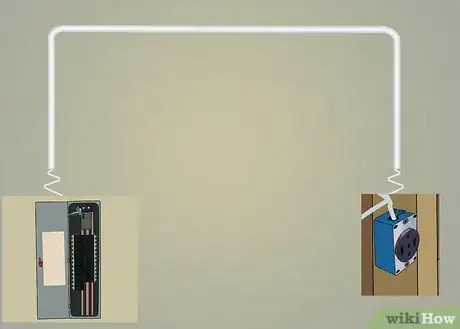
Provide power to a new outlet that will supply 220 to 240 volts for use by an electric range or other appliance such as a dryer. The steps below describe electrical service panels, wire colors and procedures commonly followed in the U.S.A. and required by the National Electrical Code. They may or may not be compatible with other areas and may be superseded by local code. This procedure describes how to wire an outlet for an electric range but can easily convert for an electric dryer (see tips section at the end of the article).
Steps
-
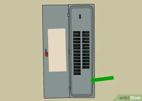
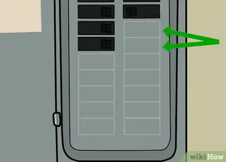
1Locate two unused spaces in the electrical service panel on one side or the other column of circuit breakers. Ultimately, the spaces must be adjacent to each other so it will be able to support a "double-wide" circuit breaker that is generally required for a 240 V circuit.[1]
-
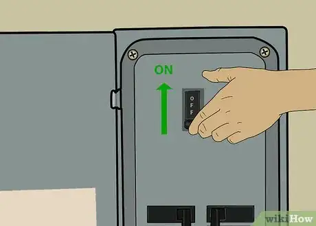
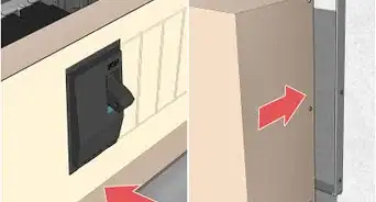
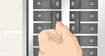
2Switch the main disconnect to the OFF position.[2] [3] The main disconnect switch is usually at the very top or very bottom of most electrical service panels, but not always. The main disconnect switch should be the largest value circuit breaker in the panel. This switch will probably be a double (or in some cases a quadruple) wide switch and be rated at 100, 200 or more amps. Leave the remaining circuit breakers in the ON position. All lights and power at outlets should now be off.Advertisement
-
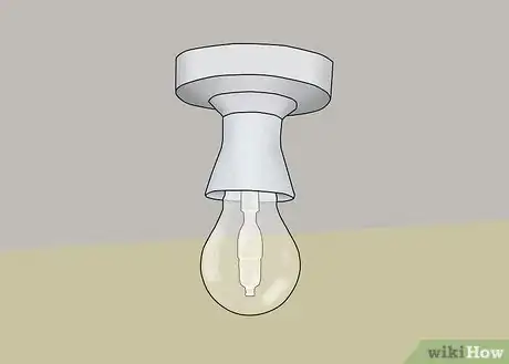
3Verify that the power is off by checking light fixtures in the space.[4]
-
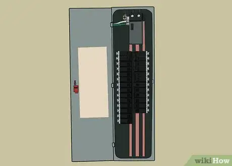
4Remove the cover on the electrical service panel. Recheck power with a meter, 120 V test light or other tester rated for 120 V by touching one probe to an unpainted surface (scratch through existing paint if needed) of the panel while touching the remaining probe to the terminals of several circuit breakers that are in the ON position. Do not proceed unless power is not present at all breakers. Only the main disconnect switch should have power on it's terminals.
-
5Locate or create a space wide enough for the new circuit breaker. If there is enough space to install the circuit breaker, skip to the next step. Otherwise, inspect the panel and assess your ability to move breakers up and / or down to create a space large enough for the breaker to fit. Some older services have two "single- wide" circuit breakers installed adjacent to each other that provide power to a single "three wire" cable (a three wire cable has a bare or green wire and three insulated wires: white, black and red). The red wire is the indicator of a three wire cable. If there is a red wire connected to a single circuit breaker, trace it back to the cable from which it originates. Once located, trace the black wire from that same cable to the point it connects to a circuit breaker. Most likely, this is the breaker directly above or below the breaker that has the red wire. Be sure to move these two single breakers as a pair. Do not create a space between these two circuit breakers to install the new circuit breaker. Do not move just one breaker to the opposite side of the panel, they must be considered as a "matched pair" only.
-
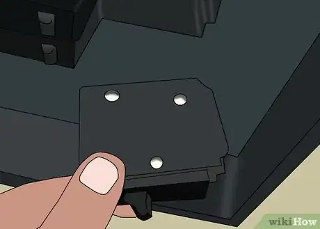
6Remove circuit breakers by moving the switch handle to the OFF position and pushing on the handle away from the middle of the panel. The circuit breaker will pop off the bus bar in the center of the panel and then it may be pulled off the side rail.
-
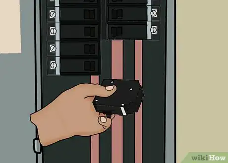
7Install the appropriately sized new circuit circuit breaker into the panel. Most circuit breakers are designed to be clipped on the side rail by aligning and pressing down at the terminal end or have a tang to engage a slot on the rail. The tang must be engaged first, and then pressed onto the bus bar in the center of the panel. This is the same as the removal procedure, but in reverse order.
-
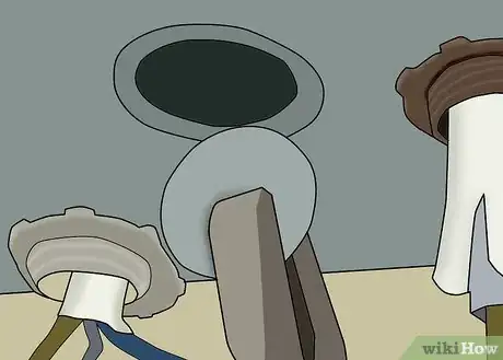
8Remove a pre-punched knock-out ("KO") from the side of the electrical panel that is the same size as the connector. Place the blade of a screwdriver at the inside-most ring and strike sharply with pliers or hammer. Carefully twist out the bent metal and continue to enlarge the opening until the circumference required by the connector is met.
-
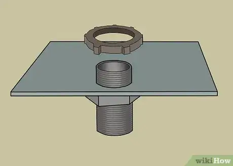
9Install the connector into the opening from the outside and spin the lock nut over the threads from inside. Hold the connector so that the screws will be readily accessible as you tighten the locknut. Once tight, drive it tight by placing the flat edge of a screwdriver in a valley of the locknut and rap sharply with pliers or hammer until tight.
-
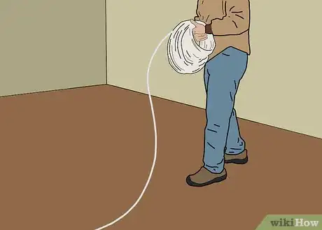
10Unroll the cable on the floor to reduce kinking during installation. The cable size and type, like the circuit breaker value, is determined by the appliance's or device's electrical requirements. A quick rule of thumb (there are variables in the Code that adjust these values up and down) is a #14 wire will supply a 12 amp load. A #12 is good for 16 amps, a #10 for 24 amps, #8 for 32 amps and #6 for 40 amps when copper cables are used. Aluminum cables can be used instead but often have additional requirements and slightly lower capacities. If installing a circuit to supply a typical 220 Volt / 30 Amp electric dryer, a cable with #10 copper conductors is required; a 220 Volt / 40 Amp electric stove would require use a cable with #6 aluminum conductors (a cable with copper conductors of this size tends to be very expensive). Local electrical code, conditions, etc. supersedes wire sizes mentioned above.
-
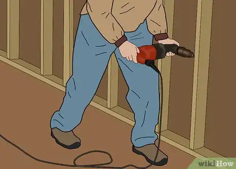
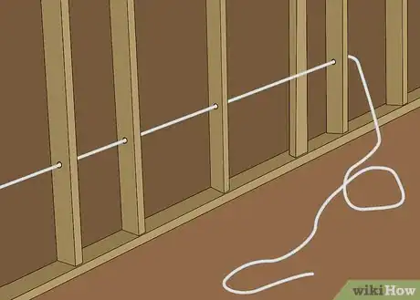
11Drill holes centered in framing members, etc. between the electrical service panel and the location of the range. Use a bit large enough to allow the cable to slide easily through. 1-1/8" would be a good choice. If old work, you will need to fish or snake the cable in the voids of walls, etc. instead.
-
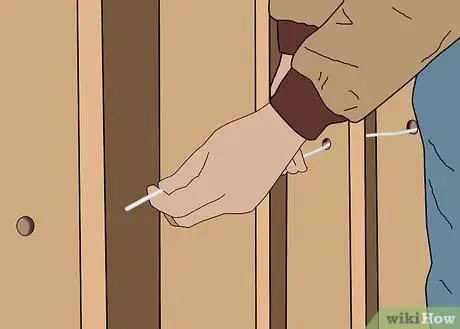
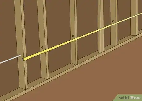
12Thread the cable through the drilled holes beginning either at the electrical panel or any point in the middle (thread in both directions).
-
13Determine where to drill behind the range to allow the cable to enter the space for the range outlet by inspecting or measuring the rear of the range. Only a space wide enough for the cable - that will not result in contact of the cable with the range frame, drawers etc. will be needed.
-
14Pass the range cable through this last hole behind the range. Leave several feet (or more) of the range cable in this area
-
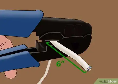
15Strip the outer jacket. Remove 6" of the jacket and any plastic shielding from around the conductors.
-
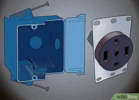
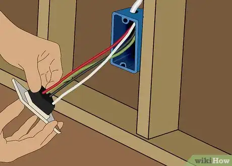
16Wire the outlet. Inspect the range outlet. Install the supplied cable connector to the range outlet with the hardware provided. It will be easier to wire the outlet if the connector is installed into the bottom of the outlet rather than the back. The bottom installation allows the cable to be easily passed into the outlet and wired without having to bend the conductors 90 degrees. Either way will work, one is just a little harder to work than the other. Lay the cable into the outlet by first lining up the jacket so that it will just be visible into the outlet body. Arrange the conductors to lay into the terminals. The black and red conductors will land in the gold terminals (it does not matter which of these two conductors land in the left or right gold terminals), the white conductor will land into the silver terminal and the uninsulated conductor will land in the green terminal. Mark them so that the conductor will extend just slightly beyond the terminal (1/16" max.)
-
17Cut the conductors for the outlet. Cut them one at a time as marked previously to allow the 1/16" extension beyond the terminal. Carefully strip the cable as per the strip gauge indicated on the range outlet. Be sure to remove all insulation from the part of the conductor that will be in the terminal.[5] Use extreme care to not nick any of the conductors. A nicked conductor must be cut back and redone. Since the working area in the outlet is so small, all the conductors will have to be re-cut to length and stripped over again.
-
18Apply oxide inhibitor. If using aluminum cable, apply a generous coating of aluminum oxide inhibitor to the individual stripped portion of the conductors and into the wire compression terminals of the range outlet (the amount of inhibitor should not be so much that it drips from the conductor or terminal). Application of oxide inhibitor to aluminum conductors is a code requirement, and must not be skipped.[6] Copper conductors however, do not require application of any oxide inhibitors.
-
19Secure the range outlet to the wall or baseboard in a location where when the range cord is connected, will not interfere with placement of the range and closing of any range drawers. Inspect the back of the range to get an idea as which locations will meet this requirement. Often times, removing the drawer will allow access to the wall - where it may be marked with a pencil, etc. Install the outlet cover and press any excess range cable back into the hole.
-
20Remove excess slack from the cable. Allow for 10" or so of slack available (should it need for later use - the cable can still be used), and pull the rest back to the electrical panel.
-
21Route the cable to the connector mounted in the electric service panel. Mark the cable jacket where it will be clamped at the locknut side of the connector. Determine how much cable will be needed to a.)connect to the new circuit breaker, b.) connect to the ground bar, and c.) connect to the neutral bar in the panel. Add 2 feet (0.6 m) or so this distance and cut the cable to this length when measured from the mark on the cable jacket.
-
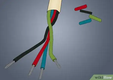
22Install the cable into the electric service panel through the cable connector. Remove the jacket and any plastic shielding from around the conductors. Untwist each of the four individual conductors.lay the cables in the electric service panel to where each will be terminated.[7]
-
23Connect to the circuit breaker. Locate an existing red wire in the panel - in either column of circuit breakers. Determine if it is connected to an ODD or EVEN numbered circuit breaker. The new red wire will be connected the same way - if existing red is EVEN then the new red will be connected to EVEN (or if existing is odd connect new to odd). Determine if the top terminal of the new circuit breaker (when installed) is the even or odd terminal. Cut to length needed, strip and install the red wire and black wires under the appropriate terminal after applying the oxide inhibitor compound to the stripped portion of the conductors.
-
24Connect to neutral and ground terminals. Most homes with a single electric service panel have one bar to provide both neutral and ground conductor terminations. If the electric service panel is a sub-panel, there should be separate bars for neutral and ground terminations. It is easy to determine, but very important to connect correctly.
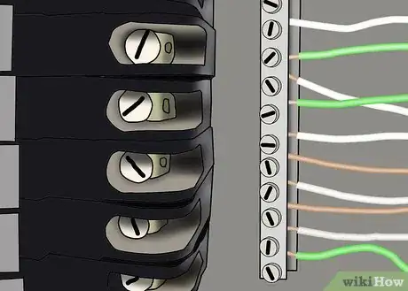
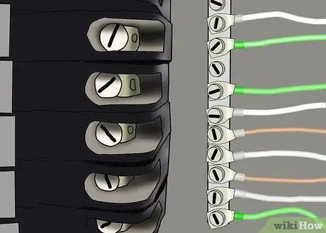
- ONE BAR If there is one bar in the electric service panel, and both the bare AND white insulated wires are connected to it, bring each of the bare and white insulated range conductors into separate unused terminals.
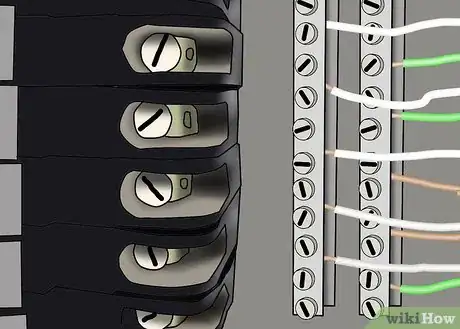
- TWO BARS If there are two bars AND one bar has all bare and/or green wires connected AND the other bar has all white wires connected, be sure to do the same - bring the range white insulated conductor to the bar with existing white conductors and the range bare to the bar with existing bare / green conductors.
- BAR AND LUGS The last configuration (and least likely to be found) is one bar with only white insulated conductors and one or more "lugs" secured to the panel back or side that have all the bare and green conductors connected. If this is the case, the range white insulated conductor will connect to the bar into an unused terminal as above, and a new lug for the range bare will be needed. This lug will have to be secured with a machine screw into a tapped hole. Sheet metal screws are not permitted to secure lugs.
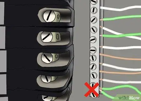
- Notice in the pictures below that there is only one wire per terminal screw. Never terminate multiple conductors under a single terminal.
-
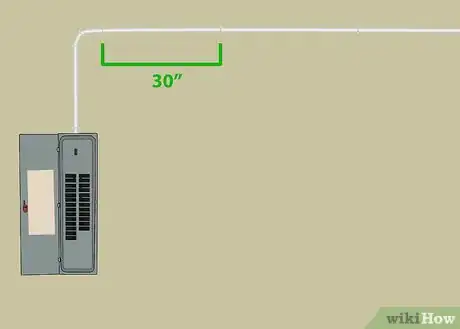
25Secure the range cable with staples where exposed as needed for support and so that there is no less than 36" between supports (every other joist or stud). Cables run through bored holes floor joists, rafters and those laying on ceiling strapping are considered supported and do not need to be stapled. Secure the cable within 18" of any electrical enclosure or box it enters.
-
26Remove the blank plates from the cover that are now occupying the place of the new circuit breaker. Check for any tools, parts or other foreign objects accidentally left in the electric service panel.
-
27Secure the cover to the electric service panel and set the new circuit breaker to OFF.
-
28Stand to the side of the panel (do not stand directly in front) and move the main service disconnect handle to ON.
-
29While still to the side, move the new circuit breaker handle to ON.
-
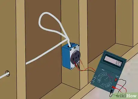
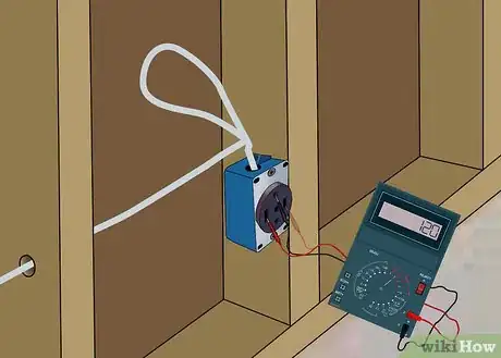
30Check for proper wiring. Using a voltmeter, check the new range outlet for proper voltages.[8]
- Check for 240V between the two flat blades openings that are parallel to each other.
- Check for 120V from the round pin opening, to each of the two previously tested parallel openings.
- Check for 120V from the flat blade opening opposite the round pin opening to each of the flat blade parallel slots first tested.
- Finally, check for 0V between the round pin opening and the flat blade opening opposite it.
-
31If any measurements are not exactly as described, turn the new circuit breaker OFF and check the wiring of the range outlet, and if necessary the wiring in the electric service panel as well. Correct any improperly wired connections and test again.
-
32Re-connecting the range. After the new outlet is wired correctly, shut off the breaker, then push the range plug into the outlet. Set the range into place.
-
33Wrap up. Update the panel directory to reflect the addition of the new circuit breaker and new positions of old circuit breaker (if any needed to be moved). Make sure all circuit breakers have been turned back on.
Expert Q&A
-
QuestionIs it hard to install a stove with a 220V line?
 Daniel StoescuDaniel Stoescu is a Master Electrician and the Owner and Operator of Home Tech Solutions, LLC in Hampton, Virginia. With over a decade of experience, Daniel specializes in wiring residential, commercial, and light industrial structures. The Home Tech Solutions team has over four decades of combined experience and offers comprehensive solutions for residential electrical needs.
Master Electrician Not really, but you must be aware that a 220V line has two hot wires. Always make sure the breaker is off and connect the two hot wires to the proper terminals, which are usually labeled with X and Y. Also make sure the connections are snug.
 -
QuestionOn a four-prong, a copper wire is attached to white. Where does the green wire go?
 Community AnswerOn a four-prong, the black and red wires are power; the white wire is neutral; and the green wire is the safety ground. But older models may only use the black and red wires for power, and the plain copper wire for the ground or neutral. You can attach the green wire to any permanent metal part of the stove for safety.
 -
QuestionDoes the stove wiring have to be under the stove, or can it be behind it?
 Community AnswerIt can be behind the stove as long as there is enough room for the wires to fit without being pinched when the stove is shoved back in place.
Warnings
- The National Electrical Code ("the code") mandates that all new range and dryer outlets be "four wire" circuits (line 1, line 2, and have separate neutral and ground conductors) and be connected to the range or dryer with a four wire cordset. Existing ranges with the older 3 wire type MUST be changed to the updated 4 wire cord-set in order to connect to the new outlet. Installing a "4 to 3 wire adapter" is not permitted. Installing a new "three wire" range outlet is also prohibited. Four wire cord-sets can be purchased inexpensively at any appliance or hardware store, and are fairly easy to connect.⧼thumbs_response⧽
- It is NOT permissible to splice SE or SER type cables.⧼thumbs_response⧽
- Aluminum conductors must only be connected to terminals that are rated for aluminum. "AL" (aluminum) and "CU/AL" (dual aluminum and copper) rated terminals, respectively. If terminals are rated "CU" only, aluminum conductors are not permitted to be connected. Most circuit breakers and range outlets have the dual rating. Double check before installing.⧼thumbs_response⧽
- Ranges and dryers are dedicated appliances, and as such, are not allowed to be connected to a circuit that is shared with another appliance or load.⧼thumbs_response⧽
- Always apply for an electrical permit before attempting this work, and have your work inspected by the local authority having jurisdiction.⧼thumbs_response⧽
- Never attempt electrical work if you do not understand what you are doing or the hazards involved.⧼thumbs_response⧽
- Never work on live electric circuits or electric service panels.⧼thumbs_response⧽
Things You'll Need
- number 6 SER type cable (10-3 copper w/ Ground Romex - dryer).
- 50 amp double pole circuit breaker (30 amp double pole type - dryer).
- staples for #6 SER cable (staples for 10-3 w/ ground romex - dryer).
- cable connector for #6 SER cable (connector for 10-3 romex - dryer).
- electric drill
- assortment of larger diameter drill bits
- screwdrivers
- pliers
- lineman pliers
- hacksaw (to cut SER cable if unable to cut with lineman pliers)
- hammer
- flashlight
- aluminum oxide inhibitor (not required if installing copper cable)
References
- ↑ https://www.youtube.com/watch?v=XMgwZDtR4tw
- ↑ https://www.youtube.com/watch?v=1KEIg4DfPTI
- ↑ Daniel Stoescu. Master Electrician. Expert Interview. 16 August 2021.
- ↑ https://www.mistersparky.com/expert-tips/how-install-outlet-your-electric-stove
- ↑ https://www.youtube.com/watch?v=1KEIg4DfPTI
- ↑ https://www.ecmag.com/section/systems/aluminum-wire-terminations-oversize-distribution-panels-and-more
- ↑ https://www.youtube.com/watch?v=1KEIg4DfPTI
- ↑ https://www.mistersparky.com/expert-tips/how-install-outlet-your-electric-stove
