wikiHow is a “wiki,” similar to Wikipedia, which means that many of our articles are co-written by multiple authors. To create this article, 23 people, some anonymous, worked to edit and improve it over time.
This article has been viewed 160,396 times.
Learn more...
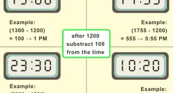
Digital clocks can be used to tell time at a glance. They became quickly more popular than the older sweep hand clocks, now known as analog clocks. The time derived by analog clocks came from either a pendulum or a spring. Pendulums are unusable on moving platforms, such as a ship, and springs unwind more and more slowly as they release stored up tension. The use of sweep hands allowed these mechanical time bases to be presented in a mechanically driven display. With the perfecting of multivibrator chips, electrical circuits could be built that could accurately keep time under a wide range of conditions. As the time base had switched from mechanical to electrical, the time display had to follow suit. Display devices called 7 segment displays were designed to allow the time to be shown numerically. While many digital clocks are available commercially, you can also build your own from components. Follow these tips to learn how to make a digital clock.
Steps
-
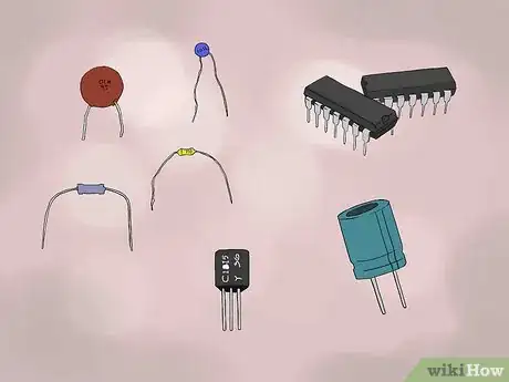
1Identify an electronics parts supplier. Many suppliers are available on the Internet or through electronics supply catalogs. Choose a vendor that offers basic integrated circuits of the generic 74xx and 40xx families, and discrete components, such as resistors and capacitors.
-
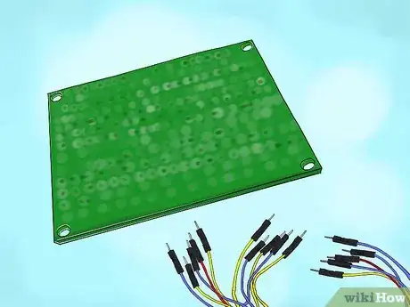
2Acquire an electronics prototyping breadboard. If the breadboard does not come with clips, which are wires that can be plugged into the breadboard to connect integrated circuits, purchase the required clips.[1]Advertisement
-
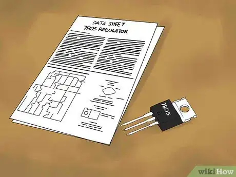
3Get the data sheet for a 7805 regulator. The data sheet will show how to wire connect the 7805 and supporting discrete components.[2]
-
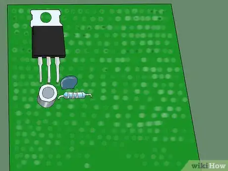
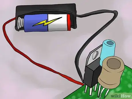
4Create a 5 volt power source. Acquire the 7805 and support components and build them up on 1 corner of the breadboard. Consult the manufacturer's data sheet for the 7805 to get the required pin-to-pin wire connections for this circuit. Plug the components into the breadboard to physically support them.[3]
-
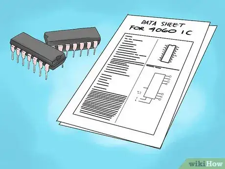
5Define a 1 Hz time base. Find the data sheet for the 4060 multivibrator integrated circuit (IC). It will show how to wire the 4060 to operate as a time generator in conjunction with a 4013 flip flop IC. Support discrete components and the wiring of the support discrete components will be shown on the data sheets.[4]
-
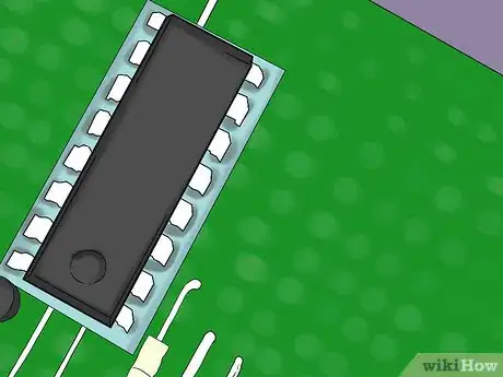
6Generate the 1 Hz time base. Acquire the 4060, 4013, breadboard sockets for those parts, and all discrete support components identified in the data sheets. Build the 1 Hz time base on 1 corner of the breadboard. Consult the manufacturer's data sheet for the 4060 to get the required pin-to-pin wire connections for this circuit. Plug the components into the breadboard to support them.
-
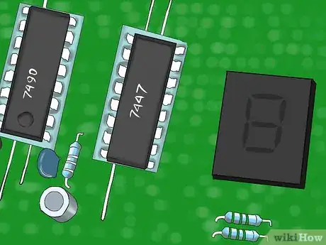
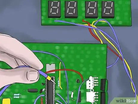
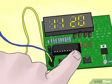
7Prepare the physical components of the clock. Mount 6 7490 counter ICs in a line on the breadboard. Mount 6 7447 display driver ICs in a line beside the 7490 ICs. Mount 6 light emitting diode (LED) displays in another line, arranged so that they are side by side as the digits of a digital clock should be. All of these devices must be plugged into breadboard sockets, which are in turn plugged into the breadboard.
-
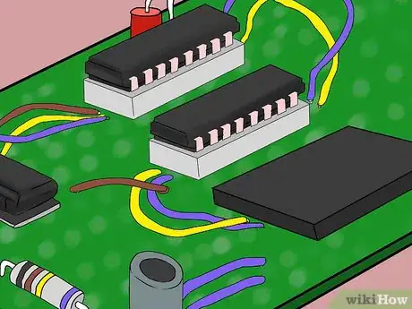
8Connect the display drivers. Wire the 7447s to the LED displays and to the 7490s, as indicated in the device data sheets.
-
9Create the counter section. Refer to the 7490 data sheets. Wiring from the rightmost device to the leftmost device, wire the first 4 7490s as a count by 10, a count by 6, a count by 10, and a count by 6. Wire the fifth 7490 as a count by 2 and the sixth 7490 as a count by 1 for the 12-hour clock. Wire the fifth 7490 as a count by 4 and the sixth 7490 as a count by 2 for the 24-hour clock.[5]
-
10Sequence the time clocking signals.
- Connect the 1 Hz time base of the clocking input (In B, pin 14) to the clocking input of the first 7490. This 7490 is the seconds counter.
- Wire pin 11 of the first 7490 to the clocking input of the second 7490. This 7490 is the tens of seconds counter.
- Provide the ability to set the minutes section of the counter. Wire the output from pin 8 of the second 7490 to the normally closed contact of a single pole double throw switch. Wire the normally open contact of the switch to the 1 Hz time base. Wire the wiper of the switch to the clock input of the third 7490. This 7490 is the minutes counter.
- Wire pin 11 of the third 7490 as the clocking input of the fourth 7490. This 7490 is the tens of minutes counter.
- Provide the ability to set the hours section of the counter. Wire the output from pin 8 of the fourth 7490 to the normally closed contact of a single pole double throw switch. Wire the normally open contact of the switch to the 1 Hz time base. Wire the wiper of the switch to the clock input of the fifth 7490. The fifth 7490 is the hours counter.
- Connect pin 6 or pin 7 of the fifth 7490 as the clocking input of the sixth 7490. This 7490 is the tens of hours counter. Use pin 6 of the fifth 7490 for the American 12-hour clock. Use pin 7 of the fifth 7490 for the 24-hour European clock.
-
11Attach the 12 volt battery to the 7805 regulator using the 12 volt battery socket.
Community Q&A
-
QuestionCan I print out the "things I need" list?
 Community AnswerYes, you can.
 -
QuestionCan I get a circuit diagram of the digital clock?
 Community AnswerDo a Google image search for "circuit diagram of a digital clock," you'll see many examples.
 -
QuestionHow do I make a powerful amplifier?
 Community AnswerLook for an MD8002A Audio Amplifier. It will provide simple circuit diagrams that you can use.
Things You'll Need
- Electronics breadboard with clips
- Integrated circuit sockets for electronic breadboarding
- Voltage regulator and support discrete electronics
- Time base generator and support discrete electronics
- Counter integrated circuits
- Light Emitting Diode (LED) display driver integrated circuits
- Display driver integrated circuits.
- Seven segment Light Emitting Diode (LED) displays
- Push button switches
- 12 volt battery and 12 volt battery socket
References
- ↑ https://www.makerspaces.com/basic-electronics/
- ↑ https://www.electroschematics.com/7805-datasheet/
- ↑ https://www.electronicsteacher.com/tutorial/building-a-5-volt-power-supply.php
- ↑ https://www.homemade-circuits.com/how-to-make-long-duration-timer-circuit/
- ↑ http://electronics-course.com/digital-clock
