This article was co-authored by Ricardo Mitchell. Ricardo Mitchell is the CEO of CN Coterie, a fully licensed and insured Lead EPA (Environmental Protection Agency) Certified construction company located in Manhattan, New York. CN Coterie specializes in full home renovation, electrical, plumbing, carpentry, cabinetry, furniture restoration, OATH/ECB (Office of Administrative Trials and Hearings/Environmental Control Board) violations removal, and DOB (Department of Buildings) violations removal. Ricardo has over 10 years of electrical and construction experience and his partners have over 30 years of relevant experience.
There are 7 references cited in this article, which can be found at the bottom of the page.
wikiHow marks an article as reader-approved once it receives enough positive feedback. In this case, 81% of readers who voted found the article helpful, earning it our reader-approved status.
This article has been viewed 834,532 times.
Relays are discrete devices (as opposed to integrated circuits) that are used to allow a low power logic signal to control a much higher power circuit. The relay isolates the high power circuit, helping to protect the lower power circuit by providing a small electromagnetic coil for the logic circuit to control. You can learn how to test both coil and solid-state relays.[1]
Steps
Preparing Your Relay
-
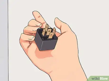
1Do a basic visual inspection of the relay. Many relays have a clear plastic shell containing the coil and contacts. Visible damage (melting, blackening, etc) will help narrow down the issue.
- Most modern relays have an LED to tell you if they are in the active state (ON). If that light is off and you've got control voltage to the relay or coil terminals (typically A1[line] and A2 [common]) then you can safely assume that relay is bad.
-
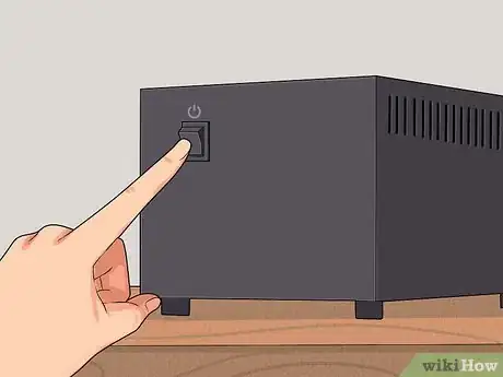
2Disconnect the power source. Any electrical work should be done with all power sources disconnected, including batteries and line voltage.[2] Be especially mindful of capacitors in the circuit, as they can hold a charge for a considerable length of time after removing the power source. Do not short capacitor terminals to discharge.[3]
- It is best to check your local laws before performing any electrical work, and if you feel unsafe, leave it to the professionals. Extra low voltage work typically will not fall under this requirement, but it's still important to be safe.
Advertisement -
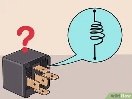
3Consult the relay schematic or data sheet. Relays have fairly standard pin configurations, but it is best to search for the data sheets to find out more about the number of pins from the manufacturer, if available. Typically, these will be printed on the relay.[4]
- Information on current and voltage ratings, pin configurations, and other information is sometimes available in the datasheets will be invaluable in testing, and eliminate most errors associated with testing. Testing pins randomly without knowing the pin configuration is possible, but if the relay is damaged, results may be unpredictable.
- Some relays, depending on their size, may also have this information printed directly on the body of the relay as well.
Testing Coil Relays
-
1Determine the coil requirements of the relay. The manufacturer's part number should be listed on the case of the relay. Look up the applicable data sheet and determine the voltage and current requirements of the control coil. This also may be printed on the case of larger relays.
-
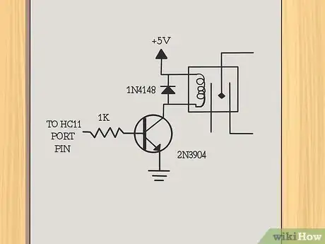
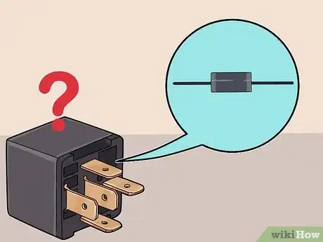
2Find out if the control coil is diode protected. A diode around the pole is often used to protect the logic circuitry from damage due to noise spikes. The diode will be shown on drawings as a triangle with a bar across one corner of the triangle. The bar will be connected to the input, or positive connection, of the control coil.[5]
-
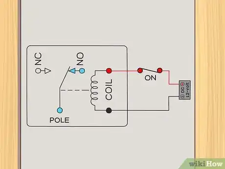
3Assess the contact configuration of the relay. This will also be available from the manufacturer's data sheet, or may be printed on the case of larger relays. Relays may have one or more poles, indicated in drawings by a single line switch connected to a pin of the relay.
- Each pole may have a normally open (NO) and or normally closed (NC) contact. The drawings will indicate these contacts as connections with a pin on the relay.[6]
- The relay drawings will show each pole as either touching the pin, indicating a NC contact, or not touching the pin, indicating a NO contact.
-
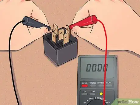
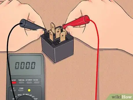
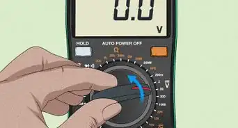
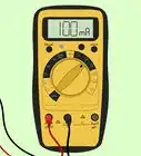
4Test the de-energized condition of the relay contacts. Use a digital multimeter (DMM) to test the resistance between each pole of the relay and the corresponding NC and NO contacts for that pole. All NC contacts should read 0 ohms to the corresponding pole. All NO contacts should read infinite resistance to the corresponding pole.
-
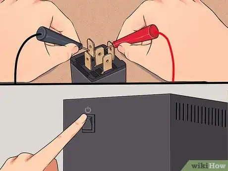
5Energize the relay. Use an independent voltage source appropriate for the rating of the relay coil. If the relay coil is diode protected, make sure that the independent voltage source is connected with the proper polarity. Listen for a click when the relay is energized.[7]
-
6Check the energized condition of the relay contacts. Use a digital multimeter (DMM) to test the resistance between each pole of the relay and the corresponding NC and NO contacts for that pole. All NC contacts should read infinite resistance to the corresponding pole. All NO contacts should read 0 ohms to the corresponding pole.
Testing Solid-State Relays
-
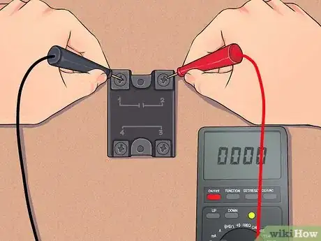
1Use an ohmmeter to check solid-state relays. When solid-state relays start to short, they will almost always fail. Solid-state relays should be checked with an ohmmeter across the normally open (N.O.) terminals when control power is off.
- The relays should be open, switched to OL, and closed (0.2 , the internal resistance of the ohmmeter) when control power is applied.
-
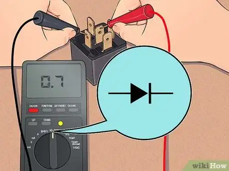
2Use a multi-meter in diode-test mode to confirm your findings. You can further confirm that the relay is bad by taking a multi-meter, put it in diode test and checking across A1(+) and A2(-). The meter will apply a small voltage to make the semiconductor conduct and read that voltage on the screen. This will check the (typically NPN) transistor from the base(P) to the... emitter.
- If its bad, the meter will read 0 or OL, but if the relay is good it will read 0.7 for a silicon transistor (which almost all of them are) or 0.5 for a germanium transistor (which are relatively rare but not unheard of).
-
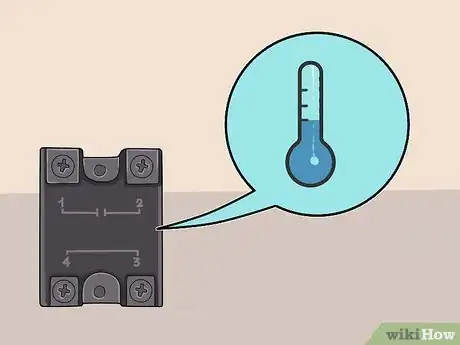
3Keep SSRs cool. Solid-state relays are easy to troubleshoot, cheap to replace and last a long time if they stay cool. Typically, new relays come in DIN rail packages and block mountings.
- There is also a special type of relay called an SCR that comes in two flavors for heating wires and IR lamps and ovens, usually for exquisite process temperature control. This is basically a fast switch on a much faster switch that can turn off and on, which fail often due to temperature fluctuations.
Expert Q&A
Did you know you can get expert answers for this article?
Unlock expert answers by supporting wikiHow
-
QuestionHow do you know if a line relay is working?
 Ricardo MitchellRicardo Mitchell is the CEO of CN Coterie, a fully licensed and insured Lead EPA (Environmental Protection Agency) Certified construction company located in Manhattan, New York. CN Coterie specializes in full home renovation, electrical, plumbing, carpentry, cabinetry, furniture restoration, OATH/ECB (Office of Administrative Trials and Hearings/Environmental Control Board) violations removal, and DOB (Department of Buildings) violations removal. Ricardo has over 10 years of electrical and construction experience and his partners have over 30 years of relevant experience.
Electrician With a line relay, you have power coming in the live wire, and a neutral wire and grounding coming into the relay. On the other end, you have an input and an output that go through a coil. If you connect the two terminals together, you should hear a click. If it clicks, the coil is good and your relay is working. If it doesn't click, your relay is bad.
Things You'll Need
- Voltage source
- Digital multimeter (DMM)
References
- ↑ https://www.explainthatstuff.com/howrelayswork.html
- ↑ https://www.ccohs.ca/oshanswers/safety_haz/electrical.html
- ↑ https://robrobinette.com/Tube_Amp_Safety.htm
- ↑ http://www.autoshop101.com/forms/hweb2.pdf
- ↑ https://electronicsclub.info/relays.htm
- ↑ https://www.electronics-tutorials.ws/io/io_5.html
- ↑ Ricardo Mitchell. Electrician & Construction Professional, CN Coterie. Expert Interview. 28 January 2021.
About This Article
If you want to test a coil rely, make sure there is no power going to it, then use a digital multimeter to test the resistance between each of the relay’s poles and their NC and NO contacts. All the NC contacts should read 0 ohms, or 0 resistance, while the NO contacts should read infinite resistance. Then, connect the relay to a power source, listen for a click, and check all of the poles again. This time, the NC contacts should have infinite resistance, and the NO contacts should have none. Keep reading to learn how to test a solid state relay!
