This article was co-authored by James Hornof. James Hornof is a Master Electrician and the Owner and President of B & W Electric based in Denver, Colorado. With over two decades of experience in the electrical construction industry, James specializes in field installation, management, estimating, and design. He graduated top of his class in electrical trade school and studied Business Management at The Community College of Denver. James holds a Master Electrician license in Colorado, Wyoming, and Texas.
This article has been viewed 251,714 times.
Install a switch to control the top outlet of an existing duplex receptacle or "electric outlet". A table lamp plugged into a switched top outlet of a duplex receptacle will allow easy lighting of the room by toggling a wall switch. This is an alternative to waving your arms while wandering about in a dark room searching for a pull chain or reaching under a lamp shade to find the switch.
Steps
Preparing for Wiring
-
1Study the diagram below, photos and step by step procedure before attempting. Do not attempt unless you have a complete understanding of the job.
-
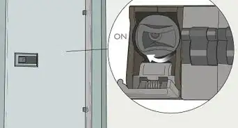
2Shut off power to the circuit.Advertisement
-
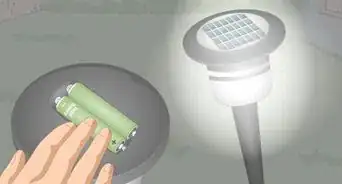
3Test the circuit with a tester or lamp prior to working to be sure power has been removed.
-
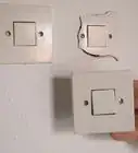
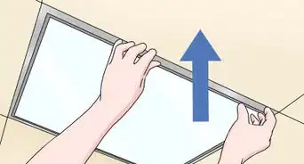
4Remove the wall plate from the receptacle and save the screws for reuse.
-
5Unscrew the receptacle from the box and save screws for reuse.
-
6Pull the receptacle gently but firmly away from the box.
-
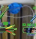
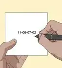
7Identify each terminal screw with a number written on masking tape, affixed close by. A booklet of adhesive numbers (like that in the photo) is great aid for a job like this.
-
8Mark the silver or white terminals with even numbers 2 and 4; the green safety ground terminal (if provided) should be marked 5. The gold terminals on the other side should be marked with odd numbers 1 and 3. Be sure to mark all terminals even if no wires are connected to them.
-
9Label each wire with the terminal number to which it is connected. Write the terminal number on a piece of masking tape and wrap around the wire's insulation. A wire under a gold screw 1 should have a 1 tag on it, while a wire under white screw 2 should have a 2 on it. The bare or green ground wire connected under terminal 5 would have a 5 tag, as in the above photos.
-
10Inspect the side of the receptacle with gold screws and locate the metal tab that connects the two square gold pads into which the gold screws are threaded. It can usually be found on the side - but close to the front of the receptacle. If it is already removed, STOP and reassemble. This installation is not covered in this wiki at this time.
-
11Disconnect all the wires from the receptacle by loosening the terminal screws. It is not required to remove the screws. The screws can not be removed unless forced.
-
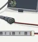
12Install an old work switchbox and run "2 wire" (two conductors AND ground conductor) Romex ® type cable of the same size wire serving the receptacle, between this old work switchbox and the receptacle (most likely 14 or 12 gauge). Do not cut cable until sure it is of sufficient length and even then leave 2 feet (0.6 m) extra before making the cut.
-
13Remove 8 inches (20.3 cm) of the cable jacket from both ends and pass the cable into each of the boxes through the opening until 1/2 to not more than 1 inch (2.5 cm) of the jacket is visible inside.
-
14Strip the new white and new black wires 1/2 to 3/4 of an inch.
-
15Identify the new white wire with a 13 tag.
-
16Identify the new black wire with a 7 tag.


Wiring the Receptacle
-
1
-
2Combine all the ground wires AND a spare piece of bare wire (or insulated wire stripped completely of insulation) and cut to 8 inches (20.3 cm), together under a properly sized wirenut.
-
3Form a hook at the loose end of the bare wire above and secure under terminal 5. Gently fold the ground wires and wirenut as far back into the box as possible.
-
4Gather all the wires with a 2 and 4 tag (most likely white wires).[3] If there is more than one wire, combine them AND a spare piece of white insulated wire cut to 8 inches (20.3 cm) and stripped 1/2 - 3/4 of an inch at the end, together under a properly sized wirenut. If there is only one wire with a 2 or 4 tag, assume it is white and go to the next step.
-
5Form a hook at the loose end of the white wire and secure under terminal 2 or 4, it does not matter which is used. Gently fold the excess wire and wirenut to the back of the box.
-
6Gather all the wires with a 1 and 3 tag (most likely black and/or red wires). Be sure to include the new white wire with a 13 tag on it (the number 13 was chosen for connection with the other 1's and 3's). Combine them AND a spare piece of black insulated wire cut to 8 inches (20.3 cm) and stripped 1/2 - 3/4 of an inch at the ends, together under a properly sized wirenut.
-
7Form a hook at the loose end of the short black wire added above and secure under terminal 1 or 3. Tag this wire with the same number as the terminal connected (1 or 3). This connected terminal is now the unswitched terminal of the receptacle, and will always be on. Gently fold the excess wire and wirenut to the back of the box.
-
8Cover or replace the tag for the unused gold terminal screw with a new 7 tag.
-
9Form a hook at the end of the new black wire with the 7 tag and tighten under the 7 terminal on the receptacle. Gently fold the excess wire to the back of the box. This is now the switched terminal of the receptacle and will be on only when the switch is set to on. If the 7 terminal is the bottom - the switched outlet will be on the bottom, conversely, if 7 is the top terminal, the switched outlet will be on the top.
-
10Secure the receptacle to the box.
-
11Secure the wall plate to the receptacle.
-
12Plug a lamp into the switched outlet of the receptacle.


Wiring the Switch
-
1Strip both of the Romex conductors 1/2 to 3/4 of an inch.
-
2Form a hook at the end of all three conductors.
-
3Connect the bare wire of the Romex cable that connects to the receptacle described above under the green screw (if provided) of the switch. If there are other ground wires in this box, the new wire should be connected to them with a wirenut and short bare wire(s) extended to each switch and other device(s) in the box. Gently fold the excess wire to the back of the box.
-
4Connect the black wire of the Romex cable that connects to the receptacle described above under either gold screw of the switch. Gently fold the excess wire to the back of the box.
-
5Connect the white wire of the Romex cable that connects to the receptacle described above under the remaining unused gold screw of the switch.
-
6Orient the switch. If the switch has "ON" and "OFF" indicated on the handle, make sure it is positioned so it can be read, and not upside-down ("FFO" and "NO").
-
7Gently fold the excess wire to the back of the box.
-
8Secure the switch to the box.
-
9Secure the wall plate to the switch.
-
10Restore power to the circuit.
-
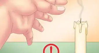
11Test the installation by operating the switch. Make sure that the switch on the lamp is set to "on" if it doesn't work at first.


Community Q&A
-
QuestionI removed an old light fixture, and there are three white wires and three black wires. Only one set is live when I close the breaker though. How do I wire it safely?
 Community AnswerAlthough this is not related to a switch-controlled outlet, this means you have one circuit coming in that then branches out to two additional connections. Since it was a light, which would be on a switch, the additional wires would most likely go to another light (or possibly already to a switch-controlled outlet). If that is the case, and you want to keep it that way, you can simply pigtail each set of matching color wires and connect the pigtail to the fan. That will basically be like plugging the fan into an outlet on that circuit that is controlled by the switch.
Things You'll Need
- Screw drivers - Phillips & straight blade types
- Lineman's Pliers
- Needle Nose Pliers (to remove tab between gold screw terminals)
- Wirenuts
-
14-2 or 12-2 Romex (must be sized the same as the outlet conductors)
- Realize that Romex ® is a brand name of NM (Non-Metallic shield) type cable (like Formica was to laminate). If Romex is not understood, try referring to it as NM type cable or "building wire".
- Single pole switch
- Old work switchbox
- Masking tape (or booklet of adhesive numbers)
- Pen, pencil or marker


References
About This Article