This article was co-authored by James Hornof. James Hornof is a Master Electrician and the Owner and President of B & W Electric based in Denver, Colorado. With over two decades of experience in the electrical construction industry, James specializes in field installation, management, estimating, and design. He graduated top of his class in electrical trade school and studied Business Management at The Community College of Denver. James holds a Master Electrician license in Colorado, Wyoming, and Texas.
This article has been viewed 298,882 times.
Resistors regulate the amount of current flowing in an electronic circuit. Resistors present a resistance, or impedance, to the electrical circuit and reduce the amount of current that is allowed to flow. Resistors are utilized for simple signal conditioning and to protect active electronic devices that could be damaged by receiving excess current. Resistors must be properly sized and intact to perform these functions. Use these tips to learn how to test resistors.
Steps
-
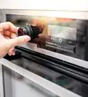
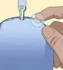
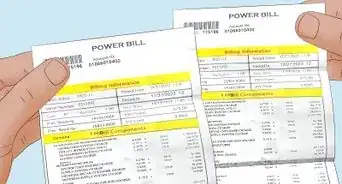
1Remove power from the circuit containing the resistor. This can be done by unplugging it from the mains or by removing the batteries if it is a portable device. Keep in mind that some devices still can be charged with a potentially harmful voltage until minutes after removing its power![1]
-
2Isolate the resistor from the circuit. An attempt to measure a resistor that is still connected to the circuit can yield an incorrect calculation, as part of the circuit might also be measured.[2]
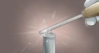
- Disconnect one end of the resistor from the circuit. It does not matter which end of the resistor is disconnected. Disconnect the resistor by pulling on the resistor. If the resistor is soldered in place, melt the solder with an electronic grade soldering iron and pull the resistor free using small needle nose pliers. Soldering irons are available at electronic parts and hobby stores.
Advertisement -
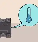
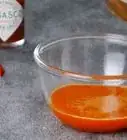
3Inspect the resistor. If the resistor shows signs of blackening or charring, it may be damaged by excess current flow. A resistor showing blackening or charring should be replaced and discarded.[3]
-
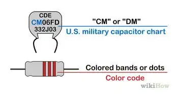
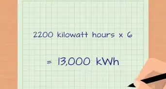
4Read the resistor value visually. The resistor value will be printed on the resistor. Smaller resistors may have their value indicated by color coded bands.[4]
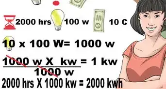
- Note the resistor tolerance. No resistor is precisely the value indicated on it. The tolerance indicates how much the printed value may vary and still be considered a properly sized resistor. For example, a 1,000 ohm resistor with a 10 percent tolerance indication is still considered to be accurate if it measures no less that 900 ohms and no more than 1,100 ohms.
-
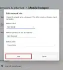
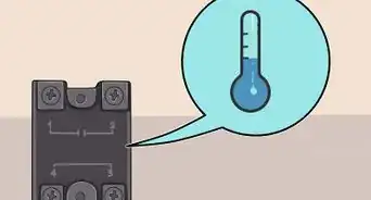
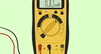
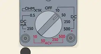
5Prepare a digital multimeter (DMM) to measure the resistor. DMMs are available at electronics parts and hobby stores.[5]
- Ensure that the DMM comes on and does not indicate a low battery condition.
- Set the adjustable scale of the DMM to the next setting higher than the expected resistor value. For example, if the DMM may be set to scales that are multiples of 10 and a resistor marked as 840 ohms is to be measured, set the DMM to the 1,000 ohm scale.
-
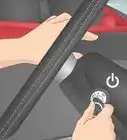
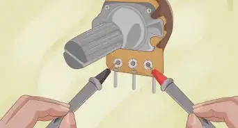
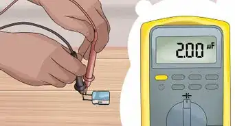
6Measure the resistance. Connect the 2 leads of the DMM to the 2 legs of the resistor. Resistors have no polarity, so it does not matter which DMM lead is connected to which resistor leg.[6]
-
7Determine the actual resistance of the resistor. Read the result shown on the multimeter. In determining whether or not the resistor is within the allowable range for that resistor, do not forget to take the resistor tolerance into account.[7]
-
8Reattach a resistor that gives an accurate reading. Reconnect it to the circuit by pressing it back into place if you pulled it free with your fingers. If the solder joint had to be melted and the resistor had to be disconnected using pliers, melt the solder with the soldering iron and use the needle nose pliers to push the resistor back in to place.
-
9Replace a resistor that measures outside of the acceptable value range. Discard the old resistor. Resistors are available in electronics parts stores and hobby stores. Note that replacing the malfunctioning resistor will not necessarily fix the problem, if the resistor fails again the source of the problem should be sought elsewhere in the circuit.


Community Q&A
-
QuestionCan you show the different colors and size pertaining to this?
 Community AnswerResistors are color-coded; one end should have a gold, silver, or white band. That band represents the resistor’s tolerance. Begin by translating the colored bands into numbers and recording those numbers. For the first and second colored bands, the values are as follows: Black = 0; Brown = 1; Red = 2; Orange = 3; Yellow = 4; Green = 5; Blue = 6; Violet = 7; Grey = 8; White = 9.
 -
QuestionWhat can cause a fuse and resistor to go bad?Community AnswerA resistor is in place to restrict current. A faulty resistor is most likely an over-current issue somewhere in the circuit. The constant heating and cooling can take its toll. A fuse can blow for multiple reasons, its primary function is circuit protection. Ideally, the fuse should blow so as to protect the other components (your resistor) in the circuit.
-
QuestionMy resistance reading is good, but I notice that there is no continuity between leads. Is that bad?Community AnswerNo, it isn't. What happened is that the resistance of your resistor was low enough to trigger a continuity reading on your multimeter. If you read your multimeter's manual or spec sheet, you will find that the maximum continuity resistance is higher than your resistor's resistance.
Things You'll Need
- Digital multimeter (DMM)
- Electronic soldering iron
- Small needle nose pliers

References
- ↑ https://sciencewithkids.com/Experiments/Energy-Electricity-Experiments/how-to-test-resistors.html
- ↑ https://www.allaboutcircuits.com/technical-articles/measuring-resistance-in-circuit-and-out/
- ↑ https://sciencing.com/happens-resistor-burns-up-8556222.html
- ↑ https://neurophysics.ucsd.edu/courses/physics_120/resistorcharts.pdf
- ↑ https://www.allaboutcircuits.com/technical-articles/measuring-resistance-in-circuit-and-out/
- ↑ https://sciencing.com/test-resistors-circuit-5989061.html
- ↑ https://sciencing.com/test-resistors-circuit-5989061.html
About This Article