This article was co-authored by wikiHow staff writer, Travis Boylls. Travis Boylls is a Technology Writer and Editor for wikiHow. Travis has experience writing technology-related articles, providing software customer service, and in graphic design. He specializes in Windows, macOS, Android, iOS, and Linux platforms. He studied graphic design at Pikes Peak Community College.
This article has been viewed 66,993 times.
Learn more...
An oscilloscope is a powerful tool used to test the voltage of an electrical signal. The oscilloscope displays the results in the form of a wave pattern on a graph, allowing you to visualize how the current behaves over time. This wikiHow article will teach you how the oscilloscope works, and how you can use it to start testing electrical signals.
Steps
Understanding the Oscilloscope
-
1Learn what an oscilloscope measures. An oscilloscope measures the voltage of an electrical current. Unlike a multimeter (which only measures the RMS voltage), an oscilloscope takes multiple voltage measurements and plots them on a graph in the form of a wave pattern. This allows you to see exactly what the voltage is doing overtime.
-
2Explore the display. The display on an oscilloscope displays voltage over time in the form of a wave pattern. This allows you to see how voltage pulses over time.[1]
- The horizontal axis on the display represents time. Usually, the time scale represented on the display is only a few milliseconds.
- The Vertical axis on the display represents voltage. The waveform on the display shows how the voltage rises and falls over time.
- The squares in the grid are called divisions. They are used to represent unit measurements How much each division represents depends on how the vertical and horizontal positioning is set on the oscilloscope.
Advertisement -
3Understand the oscilloscope channels. Most oscilloscopes have between two to four channels. Each channel has a separate input that you can connect a probe to. This allows you to measure multiple components at a time. The waveform that each probe measures is represented with a different color on the display.
-
4Learn the difference between periodic and non-periodic waves. Waves that produce a consistent pattern that does not change over time are called periodic waves. Waves that are constantly changing and do not produce a predictable pattern are called non-periodic waves. Non-periodic waves are usually caused by some external input, such as user controls (knobs and buttons, etc.), atmospheric interference, or something the circuit is measuring.
-
5Know the different types of waves. There are a variety of different types of waves patterns you will see in an oscilloscope display. These correspond to the different types of electrical currents you might be measuring. Some of these waves are as follows:
- Sine Waves: A sine wave consistently oscillates up and down producing smooth-looking waves that gradually rise, crest, and then gradually fall. Sine waves are most commonly found when measuring alternating current (AC).
- Square waves: When measuring direct current (DC), the oscilloscope will display a flat line representing the voltage. Many digital and time-based components pulse on and off thousands of times a second. This produces square or rectangle-shaped waves that rise suddenly when the current is on, and then drop suddenly when the current is off. This is sometimes referred to as a pulse wave.
- Triangle waves: Triangle waves rise consistently, peak, and then drop consistently at the same rate This produces triangle-shaped waves. Waves that rise consistently and then drop-off suddenly (or rise suddenly and drop-off consistently) are called sawtooth waves. They are often found in analog-to-digital conversion circuits, switch mode power supplies, and motor driver control circuits.[2]
- Complex waves: Complex waves are generally non-periodic waves and may contain a combination of any of the above waves.
-
6Understand what an oscilloscope can show you. Oscilloscopes measure voltage, but there are lots of other measurements you can make with an oscilloscope. These include the following:[3]
- Voltage: Voltage is the maximum amount of electrical potential between two points of a circuit. This is usually a circuit component and the ground. You can determine the voltage by subtracting the minimum point of a wave from the maximum point of a wave.
- Frequency: In addition to measuring how much voltage is in an electric current, you can also measure the amount of time in between each wave.
- Wave length: Using an oscilloscope, you can measure the length of each wave or pulse in an electrical current.
- Slope length: You can also use an oscilloscope to measure how long it takes each wave to rise to it's peak and then drop back down again.


Adjusting the Probe Compensation
-
1Turn on the oscilloscope. The coaxial cable of your probe can interfere with your measurements. Especially when taking measurements of more than a few MHz. In order to get the most accurate reading, you must adjust the compensation on the probe.
- You don't need to adjust the probe compensation every time you use the oscilloscope, but it is a good idea to check it once and a while.
-
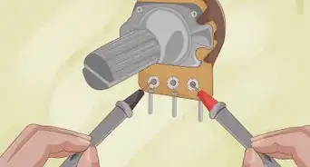
2Connect the probe to Channel 1 and turn it on. Connect the probe to the Channel 1 input, and then press the button to turn on Channel 1. Make sure all other channels are turned off.
-
3Switch the probe to "10x." Most probes have a switch that allows you to adjust the attenuation. The 1x setting is good for currents of only a few MHz, and does not need to be compensated. However, the 10x setting is used for higher electrical signals and is what you will be using most often. This needs to be compensated in order to get the most accurate reading.
-
4Attach the probe to the frequency generator. Most oscilloscopes have a frequency generator on the front of the panel. Connect the tip of the probe to the frequency generator.
-
5Attach the ground connector to the frequency generator ground. The wire that hangs loose on the probe is the ground wire. Attach it to the ground on the frequency generator.
-
6Check the display. You will likely see a square wave pattern on the display. However, they may not be perfect squares. If there is a sharp point or curve after the rise or fall of the wave, this means the probe is not compensated properly.
- If you can't see the waveform on the display, adjust the vertical and horizontal position knobs until you can see the waveform on the display.
-
7Adjust the compensation on the probe. Most probes have a screw-head on the probe, or near the base where it connects to the oscilloscope. Use a small flathead screwdriver to turn the screw-head and adjust the compensation. Turn the screw-head until the square patterns in the display are perfectly square-shaped.


Measuring a Signal
-
1Connect the probe to your oscilloscope. Connect the probe to the input on one of the channels using the probe plug.
-
2Select "1x" or "10x" on the probe. Many oscilloscope probes have a switch that allows you to switch between "1x" and "10x." The 10x setting attenuates the probe by a factor of 10. 1x is good for frequencies of less than a few MHz, but for most applications, you will want to use 10x.
-
3Turn on the channel the probe is plugged into. Look for a button above the channel probe input that toggles the channel on and off. Press it to turn the channel on. Make sure any channels you are not using are turned off.
-
4Connect the ground of the probe to a ground on your circuit. The ground is the loose wire that hangs off the side of the probe. Connect it to a ground on your circuit.
-
5Connect the probe to the output of a circuit component. The output is where the current exits the component. Most oscilloscope probes have a spring-loaded grip that is used to wrap around wires or pins.
- On most probes, you can remove the grip to reveal a smaller single-pin probe that can be used to connect hard-to-reach places on a circuit.
-
6Adjust the horizontal knob. The horizontal knob on an oscilloscope adjusts the time scale of the display, making the time scale larger or smaller. This effectively zooms in and out on the time measurement in the display.
-
7Adjust the vertical knob. The horizontal knob adjusts the voltage reading. This makes the peaks and crests of the waves bigger or smaller. This effectively zooms in and out on the vertical measurements of the wave.
-
8Adjust the horizontal position knob. This is usually a smaller knob above the horizontal knob. The smaller horizontal position knob adjusts when the time measurement in the display starts.
-
9Adjust the vertical position knob. This is usually a smaller knob above the vertical knob. This moves the wave in the display up and down.
- Some oscilloscopes have a single knob that adjusts the vertical and horizontal positions.
-
10Adjust the trigger knob to stabilize the wave measurement. If the wave in the display appears jittery, this is because the oscilloscope doesn't know when to start and stop measuring the wave. Adjust the trigger knob so that the trigger line in the display is somewhere between the minimum and maximum peaks of the waveform. This tells the oscilloscope to start measuring when the wave reaches a certain voltage.
- Most oscilloscopes allow you to select if you want the trigger to start on the rise or fall of a wave.
-
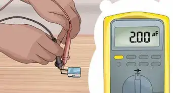
11Press the measure button. The display will display some automatic measurements, such as peak-to-peak voltage and the frequency of the waveform.[4]
- Many oscilloscopes have cursors that allow you to measure a specific section of a wave. To use the cursors, press the "Cursor" button, and then select if you want to use vertical or horizontals cursors. Use that adjustment knob to position the A cursor in the display. Then select the B cursor and use the adjustment knob to position the B cursor.


Measuring a Non-periodic Signal
-
1Power on the oscilloscope. When taking a measurement of a periodic wave, you can just connect the probe to a circuit and it will display a consistent signal on the display. Non-periodic signals can be more sporadic with signals appearing and disappearing before you can read them. To capture this type of signal, you need to set a trigger to tell the oscilloscope when to start measuring and then to only take a single sweep so that it stops taking measurements after the initial measurement.
-
2Connect the probe to your oscilloscope. Plug the probe into the input of the channel you want to use on the oscilloscope.
-
3Select "1x" or "10x" on the probe. Many oscilloscope probes have a switch that allows you to switch between "1x" and "10x." The 10x setting attenuates the probe by a factor of 10. 1x is good for frequencies of less than a few MHz, but for most applications, you will want to use 10x.
-
4Turn the channel on. Look for a button above the channel probe input that toggles the channel on and off. press it to turn the channel on. Make sure any channels you are not using are turned off.
-
5Connect the ground of the probe to a ground on your circuit. The ground is the loose wire that hangs off the side of the probe. Connect it to a ground on your circuit.
-
6Connect the probe to the output of a circuit component. The output is where the current exits the component. Most oscilloscope probes have a spring-loaded grip that is used to wrap around wires or pins.
-
7Adjust the vertical and horizontal knobs as needed. Use the positioning knobs to adjust the display so that you can see the waveform clearly in the display.
-
8Set the trigger within the waveform. Adjust the trigger knob so that the trigger line in the display is somewhere between the minimum and maximum wave points in the waveform.
-
9Press the "Single" button. Most oscilloscopes have a button that tells the oscilloscope to only take a single measurement. This tells the oscilloscope to only do a single sweep rather than continually taking new measurements and refreshing the display. This allows you to measure non-periodic waves using the oscilloscope.


Warnings
- If you are unsure of the input voltage you are measuring, wind the amplitude control up to the highest voltage before you connect the probe.⧼thumbs_response⧽
Things You'll Need
- Oscilloscope
- Oscilloscope probe


References
About This Article

1. Connect the probe to channel input and turn the channel on.
2. Select "1x" or "10x" on the probe.
3. Attach the ground wire on the probe to the ground on the circuit.
4. Attach the probe to the output of a circuit component.
5. Adjust the horizontal knob to adjust the time scale in the display.
6. Adjust the vertical knob to adjust the voltage reading in the display.
7. Use the small knobs to shift the wave in the display, up, down, left, or right.
8. Adjust the trigger knob within the wave voltage to stabilize the waveform.
9, Press the Measure button to take some automatic measurements.