This article was co-authored by Mantas Silvanavicius. Mantas Silvanavicius is a Licensed Electrician and the Owner of M+S Electric based in Las Vegas, Nevada. With more than 20 years of experience, he specializes in home electrical installations, testing, and wiring. Mantas and his team have completed projects for companies such as Seiko and Springhill Suites by Marriott. M+S Electric is licensed, bonded, and insured.
This article has been viewed 50,572 times.
Ohm’s law describes the fundamental way in which electrical circuits behave. There is a direct relationship between current, resistance and voltage. Ohm’s law also states that resistance is a constant independent of both current and voltage.[1] If you have some wire that you don’t know the resistance of, you can calculate it simply by measuring the current and voltage running through the wire and then plugging it into Ohm’s law.
Steps
Setting up the Test Circuit
-
1Gather the necessary materials. To properly set up a circuit to test the resistance of a wire, you will need a breadboard with banana plug connectors, a voltmeter, an ammeter, 5 wires with banana plugs on both ends, a DC power supply, and the wire you are testing.[2] All of these components can be purchased online or at an electronics store.
- A breadboard is a piece of plastic with many holes that can be connected together to form circuits.[3] The banana plug connectors make it easier to construct the circuit.
- Alternatively, you can use two multimeters instead of one voltmeter and one ammeter. Set one multimeter to the voltage setting (positions labeled V) and one multimeter to the ammeter setting (positions labeled A).
- It’s recommended to get the banana plug wires in five different colors to easily spot errors in the circuit setup (white, black, purple, green, and orange).
-
2Connect the ammeter to the positive end of the power supply. Make sure the power supply and ammeter are off during the construction of the circuit. Using the white banana plug wire, attach one end of the wire to the port of the multimeter that reads 10ADC and plug the other end into the positive terminal of the DC power supply.[4]
- Make sure the multimeter is set to a position labeled “A”.
- Use caution setting up the circuit. If the power supply is left on, it can damage your instruments and you could get a small shock while plugging things in.
Advertisement -
3Connect the ammeter to the breadboard. Using a second wire with banana plugs (black), plug in one end of the wire to the COM port of the multimeter and then insert the other end to the plug connector attached to the breadboard.[5]
- The ammeter will be connected in series with the rest of the circuit.
-
4Connect the voltmeter to the ammeter. Taking a new wire with banana plug ends (purple), insert one end into the VΩ port of the voltmeter. Take the other end and insert it into the top of the black banana plug that connects the ammeter to the breadboard.[6]
-
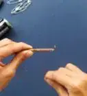
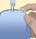
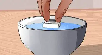
5Insert the wire into the breadboard. Next to the black/purple stack insert one end of the wire into one slot of the breadboard and the other end further down on the breadboard.[7]
- If the wire is insulated (has a plastic coating) make sure to remove enough of the insulation from the ends so that only exposed wire is inserted into the breadboard.
-
6Connect the negative terminal of the power supply to the breadboard. With the green wire, plug one end of the wire into the negative terminal of the power supply and insert the other end of the banana plug wire directly next to the wire that you’re testing.[8]
- At this stage, the positive terminal of the power supply should be connected to the ammeter and the negative terminal connected to the breadboard next to the experimental wire.
-
7Connect the voltmeter to the power supply. This is the final connection to complete the circuit. With the orange wire plug one end into the COM port of the voltmeter and then insert the other end into the top of the green wire that is connected to the power supply.[9] This configuration is essential to the entire circuit working properly.
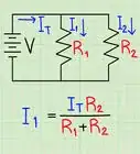
- The voltmeter is now connected in parallel to the rest of the circuit.
-
8Turn on the ammeter. Make sure the ammeter is set to DC. Also set the ammeter to the highest amperage setting (usually 10A) to avoid damaging the equipment.[10]
- If you don’t see any readings after turning the power supply on, turn it down to the lower amperage setting (usually 400mA).
-
9Power on the voltmeter. Make sure the voltmeter is turned to the position labeled V with two lines over it: one dashed and one solid. This indicates DC voltage which is what you are working with.[11]
- If don’t see any readings try changing the settings from V (volts) to mV (millivolts).
-
10Turn the power supply on. Make sure the power supply is plugged in and turn it on. You should immediately see readings on both the ammeter and the voltmeter. With the circuit set up this way, you can use the readings from both of these meters to calculate the resistance through the wire.[12]
- Record the readings for current from the ammeter and voltage from the voltmeter.
- Ensure everything is properly connected and tightly plugged in before turning on the power supply.


Calculating Resistance
-
1
-
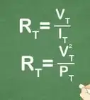
2Rearrange Ohm’s law to solve for resistance. Because you want to calculate the resistance of the wire, you will need to rearrange the equation to solve for resistance. This yields R = V/I. If you experimentally determine the amount of current and voltage going through the wire, you can calculate the resistance.[15]
-
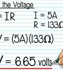
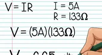
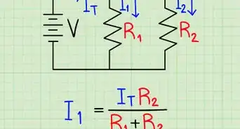
3Plug in experimentally determined figures. Using the experimental results you obtained from your circuit, you can calculate the resistance of the wire in question. Plug in the numbers for the current (I) obtained from the ammeter and voltage (V) obtained from the voltmeter from your circuit into the equation.
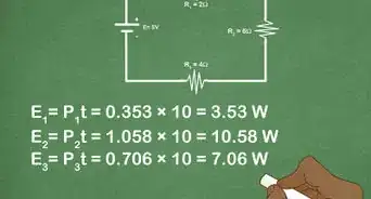
- For example: After setting up your circuit, you found that the current was 10 amps and the voltage was 100 volts. R = V/I = 100/10.
-
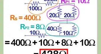
4Solve for resistance. Once you have plugged in the numbers, simply take voltage divided by current to solve for the resistance of the wire.
- For example: R = V/I = 100/10 = 10 ohms. The resistance of the wire is 10 ohms.


Troubleshooting the Circuit
-
1Ensure all components are tightly connected. Tight connections are essential to completing the circuit. If one of the components is loosely connected you might end up with an open circuit, or a place where the electricity cannot continue to flow. Making sure everything is tight ensures a closed circuit.
-
2Make sure the circuit is arranged correctly. All of the components of the circuit must be arranged in the proper order or it will not work. You could end up with an incomplete circuit or components in the wrong sequence which can lead to equipment failure.[16]
- Check each step and make sure you connected everything exactly as it says to do.
- Draw a circuit diagram to use a map for all of your components and connections.
-
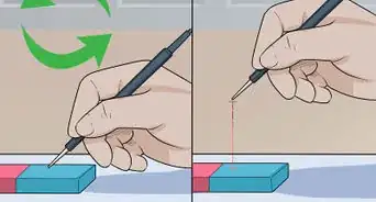
3Remove insulation from the ends of the wire. If the wire you are testing has a plastic coating on it (insulation) this can impede the flow of electrons through the circuit. Any pieces of wire that are plugged into the breadboard need to be free of insulation.[17]
- Use wire strippers to cut away the insulation from the ends of the wire before inserting into the breadboard.[18] If you’re still having trouble, try trimming more of the insulation off the wire.
-
4Make sure the power supply is working. This may seem obvious, but checking the power supply is an easy fix if that’s what is wrong. Make sure it is plugged in and that the outlet it is plugged into is working. If it’s plugged in and doesn’t turn on, you might need to replace the power source.


Community Q&A
-
QuestionA conductor has how many valence electrons?
 Community AnswerCharge (Q) = I (current) x T (time), then divide charge by charge of electron.


References
- ↑ http://www.pa.msu.edu/courses/2014spring/PHY252/Lab2.pdf
- ↑ http://www.pa.msu.edu/courses/2014spring/PHY252/Lab2.pdf
- ↑ http://www.allaboutcircuits.com/textbook/direct-current/chpt-5/building-simple-resistor-circuits/
- ↑ http://www.pa.msu.edu/courses/2014spring/PHY252/Lab2.pdf
- ↑ http://www.pa.msu.edu/courses/2014spring/PHY252/Lab2.pdf
- ↑ http://www.pa.msu.edu/courses/2014spring/PHY252/Lab2.pdf
- ↑ http://www.pa.msu.edu/courses/2014spring/PHY252/Lab2.pdf
- ↑ http://www.pa.msu.edu/courses/2014spring/PHY252/Lab2.pdf
- ↑ http://www.pa.msu.edu/courses/2014spring/PHY252/Lab2.pdf
- ↑ http://www.pa.msu.edu/courses/2014spring/PHY252/Lab2.pdf
- ↑ http://www.pa.msu.edu/courses/2014spring/PHY252/Lab2.pdf
- ↑ http://www.pa.msu.edu/courses/2014spring/PHY252/Lab2.pdf
- ↑ http://hyperphysics.phy-astr.gsu.edu/hbase/electric/resis.html
- ↑ http://www.pa.msu.edu/courses/2014spring/PHY252/Lab2.pdf
- ↑ http://hyperphysics.phy-astr.gsu.edu/hbase/electric/resis.html
- ↑ http://www.pa.msu.edu/courses/2014spring/PHY252/Lab2.pdf
- ↑ http://makezine.com/projects/perfect-jumper-wires/
- ↑ https://learn.sparkfun.com/tutorials/working-with-wire